Functional Safety RM0046
740/936 Doc ID 16912 Rev 5
Module registers (MR0–6143)
This is the lower 6 KB module memory space that holds all the functional registers of the
module that is protected by the register protection module.
Module Register and Set Soft Lock Bit (LMR0–6143)
This is memory area #3 that provides mirrored access to the MR0–6143 registers with the
side effect of setting Soft Lock Bits in case of a write access to a MR that is defined as
protectable by the locking mechanism. Each MR is protectable by one associated bit in a
SLBRn[SLBm], according to the mapping described in Table 388.
Soft Lock Bit Register (SLBR0–1535)
These registers hold the Soft Lock Bits for the protected registers in memory area #1.
Table 389 gives some examples how SLBRn[SLB] and SLBRn[MRn] go together:
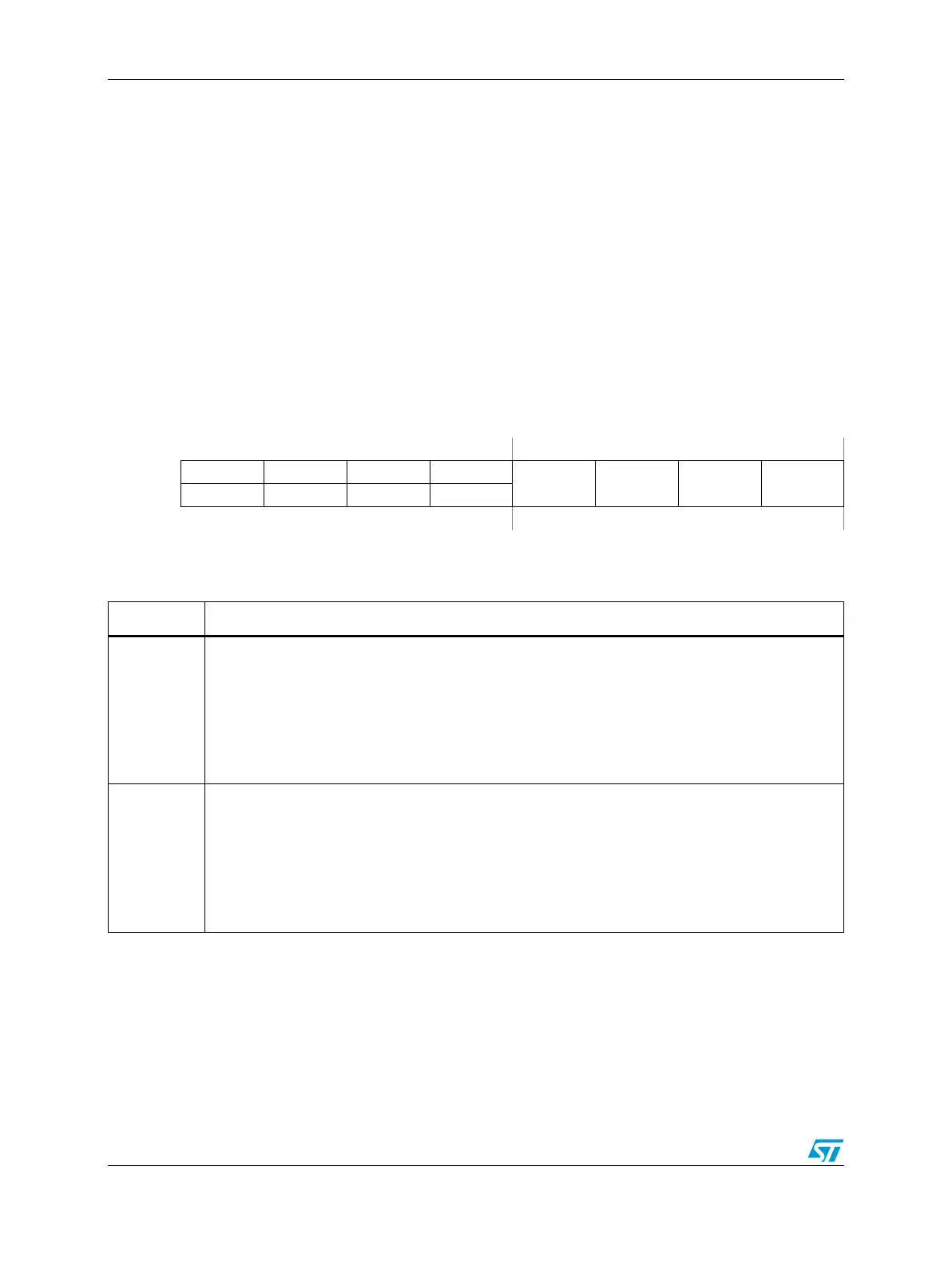
Figure 420. Soft Lock Bit Register (SLBRn)
Address:
Base + 0x3800–0x3DFF Access: User read-only; Supervisor read/write
01234567
R0000
SLB0 SLB1 SLB2 SLB3
W WE0 WE1 WE2 WE3
Reset00000000
Table 388. SLBRn field descriptions
Field Description
WE0
WE1
WE2
WE3
Write Enable Bits for Soft Lock Bits (SLB):
WE0 enables writing to SLB0.
WE1 enables writing to SLB1.
WE2 enables writing to SLB2.
WE3 enables writing to SLB3.
0 SLB is not modified.
1 Value is written to SLB.
SLB0
SLB1
SLB2
SLB3
Soft Lock Bits for one MRn register:
SLB0 can block accesses to MR[(n ×4)+0]
SLB1 can block accesses to MR[(n ×4)+1]
SLB2 can block accesses to MR[(n ×4)+2]
SLB3 can block accesses to MR[(n ×4)+3]
0 Associated MRn byte is unprotected and writeable.
1 Associated MRn byte is locked against write accesses.