FlexCAN RM0046
568/936 Doc ID 16912 Rev 5
Overload frames
FlexCAN does transmit overload frames due to detection of following conditions on CAN
bus:
● Detection of a dominant bit in the first/second bit of Intermission
● Detection of a dominant bit at the 7th bit (last) of End of Frame field (Rx frames)
● Detection of a dominant bit at the 8th bit (last) of Error Frame Delimiter or Overload
Frame Delimiter
Time stamp
The value of the Free Running Timer is sampled at the beginning of the Identifier field on the
CAN bus, and is stored at the end of “move-in” in the TIME STAMP field, providing network
behavior with respect to time.
Note that the Free Running Timer can be reset upon a specific frame reception, enabling
network time synchronization. Refer to TSYN description in Section , “Control Register
(CTRL).
Protocol timing
Figure 276 shows the structure of the clock generation circuitry that feeds the CAN Protocol
Interface (CPI) sub-module. The clock source bit (CLK_SRC) in the CTRL Register defines
whether the internal clock is connected to the output of a crystal oscillator (Oscillator Clock)
or to the Peripheral Clock (generally from a PLL). In order to guarantee reliable operation,
the clock source should be selected while the module is in Disable Mode (bit MDIS set in the
Module Configuration Register).
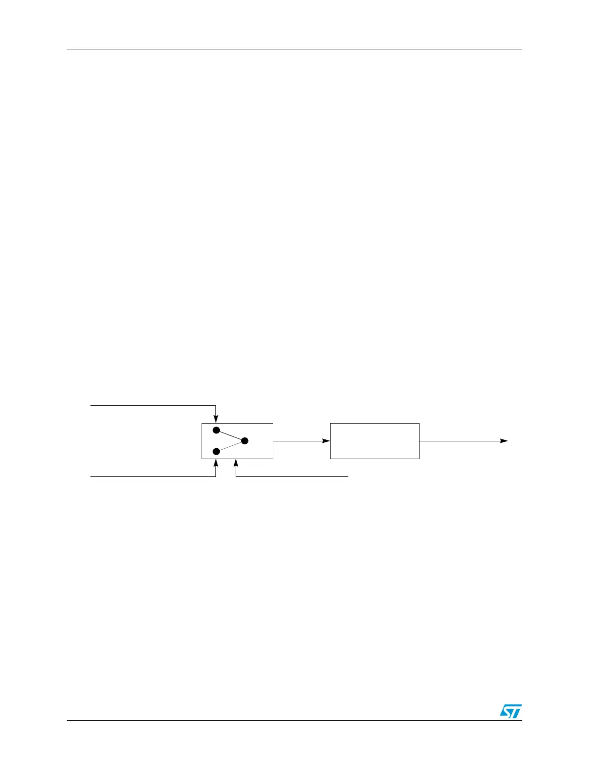
Figure 276. CAN engine clocking scheme
The crystal oscillator clock should be selected whenever a tight tolerance (to 0.1%) is
required in the CAN bus timing. The crystal oscillator clock has better jitter performance
than PLL generated clocks.
Note: This clock selection feature may not be available in all MCUs. A particular MCU may not
have a PLL, in which case it would have only the oscillator clock, or it may use only the PLL
clock feeding the FlexCAN module. In these cases, the CLK_SRC bit in the CTRL Register
has no effect on the module operation.
The FlexCAN module supports a variety of means to setup bit timing parameters that are
required by the CAN protocol. The Control Register has various fields used to control bit
timing parameters: PRESDIV, PROPSEG, PSEG1, PSEG2 and RJW. See Section ,
“Control Register (CTRL).
Peripheral Clock (PLL)
Oscillator Clock (Xtal)
CLK_SRC
Prescaler
(1 .. 256)
Sclock
CPI Clock