Cross Triggering Unit (CTU) RM0046
606/936 Doc ID 16912 Rev 5
double-buffered register (TGSCRR), during the control cycle n – 1 and reloads all the
double-buffered registers (such as Trigger Compare registers, TGSCR, TGSCRR itself).
The triggers list registers consist of eight compare registers. Each triggers list register is
associated with a comparator. On reload (MRS occurrence), the comparators are disabled.
One TGS clock cycle is necessary to enable them and to start the counting. The MRS is
output together with individual trigger signals. The MRS can be performed by hardware or
by software. The MRS_SG bit in the CTU control register, if set to 1, generates equivalent
software MRS (that is, resets/reloads TGS Counter and reloads all double-buffered
registers). This bit is cleared by each hardware or software MRS occurrence.
The TGS counter compare register and the TGS counter comparator are used to stop the
TGS counter when it reaches the value stored in the TGS counter compare register before
an MRS occurs.
The prescaler for TGS and SU can be 1,2,3,4 (PRES bits in the TGS Control Register).
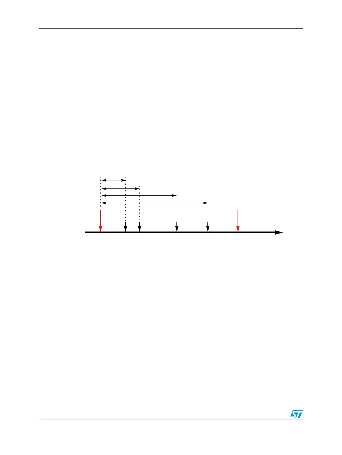
An example timing for the TGS in Triggered Mode is shown in Figure 303. The red arrows
indicate the MRS occurrences, while the black arrows indicate the trigger event
occurrences, with the relevant delay in respect to the last MRS occurrence.
Figure 303. Example timing for TGS in triggered mode
24.3.4 TGS in sequential mode
The structure of the TGS in sequential mode is shown in Figure 304.
The 32 input events (16 signals with two edges for signal), which can be individually
enabled, are ORed in order to generate the event signal (ES). The ES enables the reload of
the TGS counter register and pilots the 3-bit counter in order to select the next active trigger.
One of the 32 input events can be selected, through the MRS_SM (master reload selection
sequential mode) bits in the TGS control register, to be the MRS, that enables the reload of
the triggers list and resets the 3-bit counter (incoming events counter), that is, the MRS is
the signal linked with the control cycle defined as the time window between two consecutive
MRSs. In this mode, each incoming event sequentially enables only one trigger event
through the 3-bit counter and the MUX. The MUX is a selection switch that enables,
according to the number of event signals occurred, only one of the eight trigger signals to
the scheduler subunit. Sequences of as many as eight trigger events can be supported
within this control cycle.
For the other features see the previous paragraphs.
Delay T
0
Delay T
1
Delay T
2
Delay T
2