Reset Generation Module (MC_RGM) RM0046
206/936 Doc ID 16912 Rev 5
The ‘functional’ reset can be optionally disabled by software writing bit
RGM_FERD.D_<functional reset>.
Note: The RGM_FERD register can be written only once between two power-on reset events.
An enabled functional reset will normally trigger a reset sequence starting from the
beginning of PHASE1. Nevertheless, the RGM_FESS register enables the further
configuring of the reset sequence triggered by a functional reset. When
RGM_FESS.SS_<functional reset> is set, the associated ‘functional’ reset will trigger a
reset sequence starting directly from the beginning of PHASE3, skipping PHASE1 and
PHASE2. This can be useful especially in case a functional reset should not reset the flash
module.
See the MC_ME chapter for details on the STANDBY0 and DRUN modes.
8.4.5 Alternate Event Generation
The MC_RGM provides alternative events to be generated on reset source assertion. When
a reset source is asserted, the MC_RGM normally enters the reset sequence. Alternatively,
it is possible for some reset source events to be converted from a reset to either a SAFE
mode request issued to the MC_ME or to an interrupt request issued to the core.
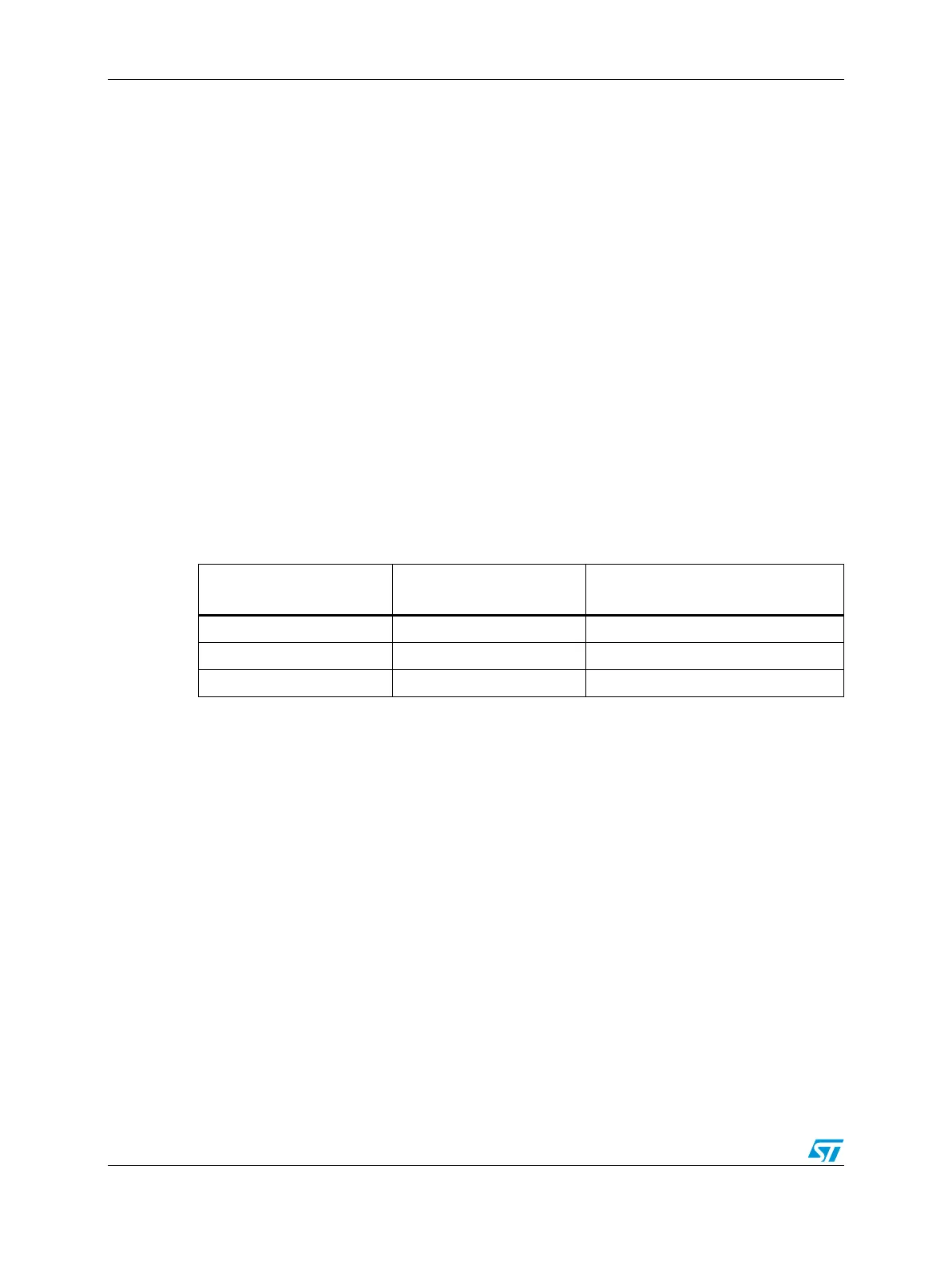
Alternate event selection for a given reset source is made via the RGM_FERD and
RGM_FEAR registers as shown in Tabl e 66 .
The alternate event is cleared by deasserting the source of the request (i.e., at the reset
source that caused the alternate request) and also clearing the appropriate RGM_FES
status bit.
Note: Alternate requests (SAFE mode as well as interrupt requests) are generated regardless of
whether the system clock is running.
Note: If a masked ‘functional’ reset event which is configured to generate a SAFE mode/interrupt
request occurs during PHASE1, it is ignored, and the MC_RGM will not send any safe
mode/interrupt request to the MC_ME.
8.4.6 Boot Mode Capturing
The MC_RGM provides sampling of the boot mode PAD[4:2] for use by the system. This
sampling is done five 16 MHz internal RC oscillator clock cycles before the rising edge of
RESET_B. The result of the sampling is then provided to the system. For each bit, a value of
‘1’ is produced only if each of the oldest three of the five samples have the value ‘1’,
otherwise a value of ‘0’ is produced.
Note: In order to ensure that the boot mode is correctly captured, the application needs to apply
the valid boot mode value to the device at least five 16 MHz internal RC oscillator clock
periods before the external reset deassertion crosses the V
IH
threshold.
Table 66. MC_RGM Alternate Event Selection
RGM_FERD
Bit Value
RGM_FEAR
Bit Value
Generated Event
0 X reset
1 0 SAFE mode request
1 1 interrupt request