Clock Description RM0046
112/936 Doc ID 16912 Rev 5
Control Status Register (CMU_0_CSR)
0x000C
Low Frequency Reference Register FMPLL_0
(CMU_0_LFREFR_A)
R/W 0x0000_0000 on page 4-114
0x0010 Interrupt Status Register (CMU_0_ISR) R/W 0x0000_0000 on page 4-114
0x0014 Reserved
0x0018 Measurement Duration Register (CMU_0_MDR) R/W 0x0000_0000 on page 4-115
0x001C–0x3FFF Reserved
Table 17. CMU memory map (continued)
Offset from
CMU_BASE
(0xC3FE_0100)
Register
Access
Reset value Location
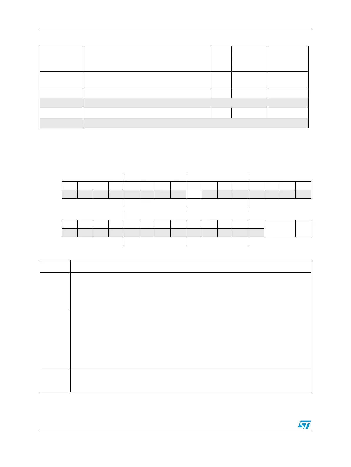
Figure 20. Control Status Register (CMU_0_CSR)
Address:
Base + 0x0000 Access: User read/write
0123456789101112131415
R00000000
SFM
000
0 000
W
Reset0000000000000000
16 17 18 19 20 21 22 23 24 25 26 27 28 29 30 31
R00000000 00000
RCDIV[1:0]
CME
_0
W
Reset0000000000000000
Table 18. CMU_0_CSR field descriptions
Field Description
SFM
Start frequency measure
The software can only set this bit to start a clock frequency measure. It is reset by hardware when the
measure is ready in the CMU_FDR.
0: Frequency measurement completed or not yet started
1: Frequency measurement not completed
RCDIV[1:0]
RC clock division factor
These bits specify the RC clock division factor. The output clock is CK_IRC divided by the factor
2
RCDIV
. This output clock is compared with CK_XOSC for crystal clock monitor feature.The clock
division coding is as follows.
00
: Clock divided by 1 (no division)
01
: Clock divided by 2
10: Clock divided by 4
11
: Clock divided by 8
CME_0
FMPLL_0 clock monitor enable
0
: FMPLL_0 monitor disabled
1
: FMPLL_0 monitor enabled