RM0046 FlexPWM
Doc ID 16912 Rev 5 663/936
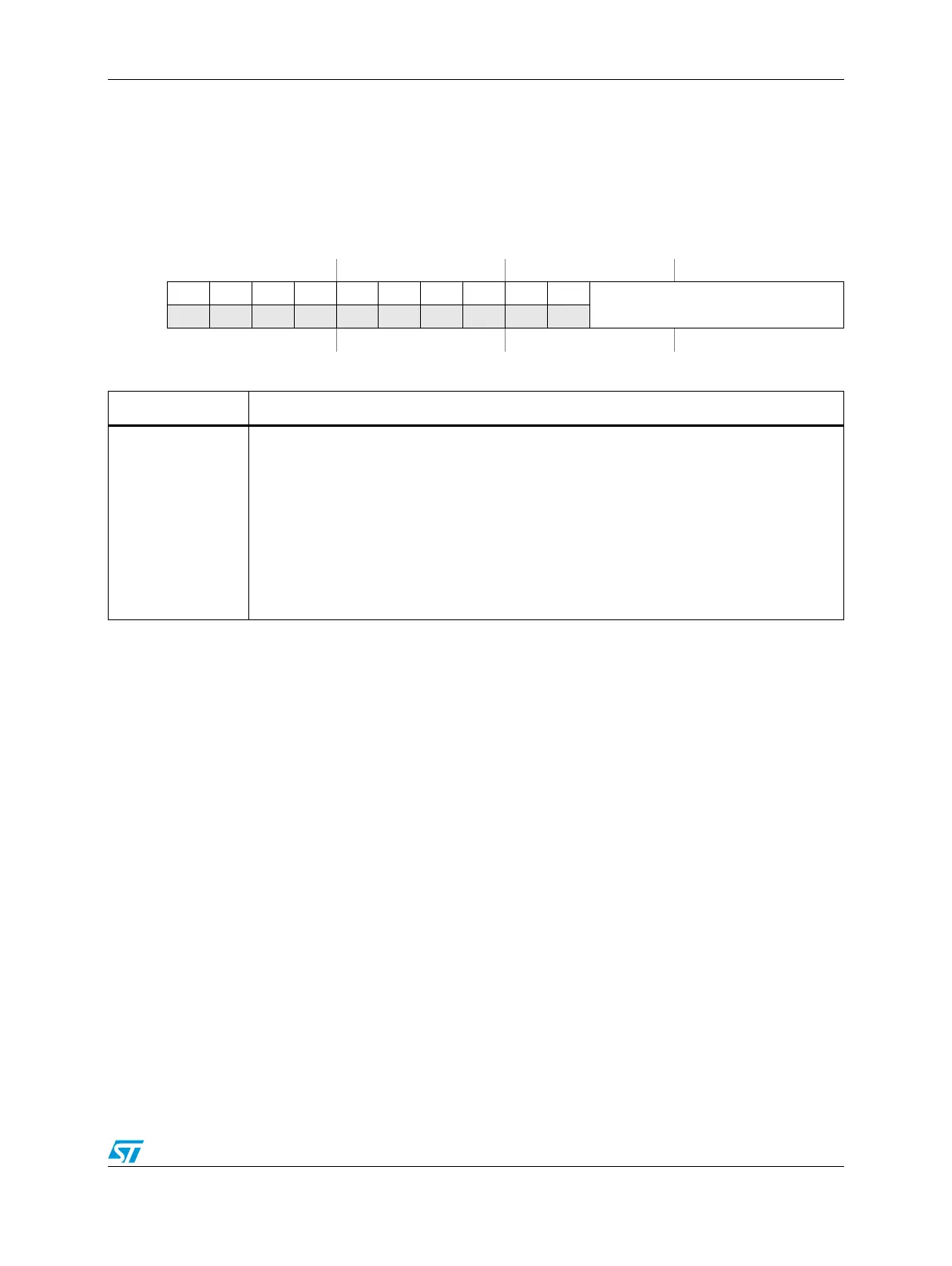
Output Trigger Control register (TCTRL)
Figure 349. Output Trigger Control register (TCTRL)
Address:
Base + 0x0020 (Submodule 0)
Base + 0x0070 (Submodule 1)
Base + 0x00C0 (Submodule 2)
Base + 0x0110 (Submodule 3)
Access: User read/write
0123456789101112131415
R0000000000
OUT_TRIG_EN[5:0]
W
Reset0000000000000000
Table 351. TCTRL field descriptions
Field Description
10:15
OUT_TRIG_EN[5:0]
Output Trigger Enables
These bits enable the generation of OUT_TRIG0 and OUT_TRIG1 outputs based on the
counter value matching the value in one or more of the VAL0-5 registers where
OUT_TRIG_EN[0] refers to VAL0, OUT_TRIG_EN[1] refers to VAL1 and so on.
VAL0, VAL2, and VAL4 are used to generate OUT_TRIG0 and VAL1, VAL3, and VAL5 are
used to generate OUT_TRIG1. The OUT_TRIGx signals are only asserted as long as the
counter value matches the VALx value, therefore as many as six triggers can be generated
(three each on OUT_TRIG0 and OUT_TRIG1) per PWM cycle per submodule.
0 OUT_TRIGx will not set when the counter value matches the VALx value.
1 OUT_TRIGx will set when the counter value matches the VALx value.