Wakeup Unit (WKPU) RM0046
778/936 Doc ID 16912 Rev 5
NMI Configuration Register (NCR)
This register holds the configuration bits for the non-maskable interrupt settings.
Note: Writing a 0 to both NREEand NFEE disables the NMI functionality completely (that is, no
system wakeup or interrupt will be generated on any pad activity)!
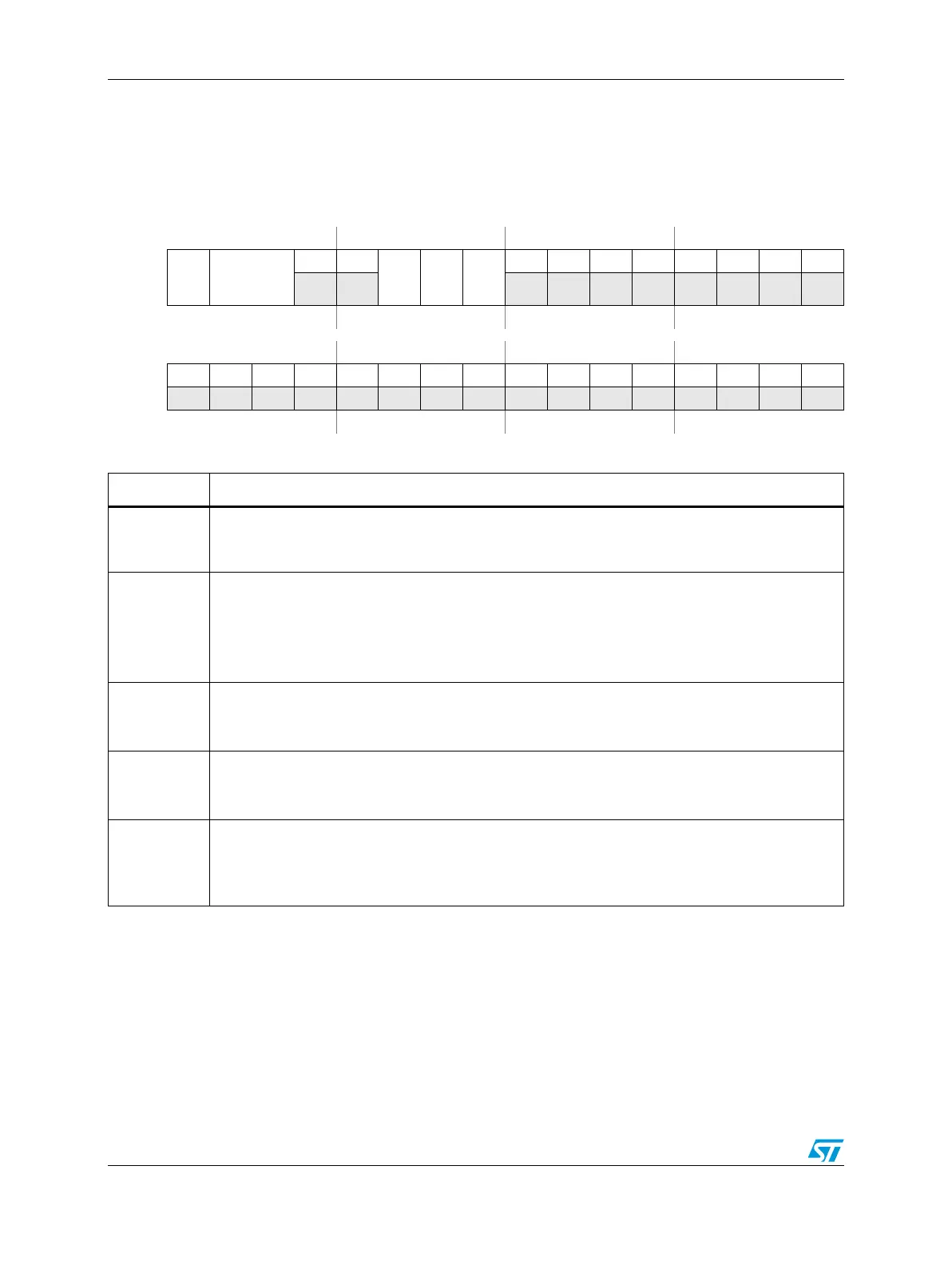
Figure 454. NMI Configuration Register (NCR)
Address:
Base + 0x0008 Access: User read/write
0123456789101112131415
R
NLOCK
NDSS
00
NREE
NFEE
NFE
00000000
W
Reset0000000000000000
16 17 18 19 20 21 22 23 24 25 26 27 28 29 30 31
R00000000 00000000
W
Reset0000000000000000
Table 416. NCR field descriptions
Field Description
0
NLOCK
NMI Configuration Lock Register
Writing a 1 to this bit locks the configuration for the NMI until it is unlocked by a system reset.
Writing a 0 has no effect.
1-2
NDSS
NMI Destination Source Select
00: Non-maskable interrupt
01: Critical interrupt
10: Machine check request
11: Reserved
5
NREE
NMI Rising-edge Events Enable
0: Rising-edge event is disabled
1: Rising-edge event is enabled
6
NFEE
NMI Falling-edge Events Enable
0: Falling-edge event is disabled
1: Falling-edge event is enabled
7
NFE
NMI Filter Enable
Enable analog glitch filter on the NMI pad input.
0: Filter is disabled
1: Filter is enabled