RM0046 FlexPWM
Doc ID 16912 Rev 5 657/936
Value register 1 (VAL1)
The 16-bit signed value written to this register defines the modulo count value (maximum
count) for the submodule counter. Upon reaching this count value, the counter will reload
itself with the contents of the INIT register. This register is not byte accessible.
Note: The VAL1 register is buffered. The value written does not take effect until the LDOK bit is set
and the next PWM load cycle begins. VAL1 cannot be written when LDOK is set. Reading
VAL1 reads the value in a buffer and not necessarily the value the PWM generator is
currently using.
Value register 2 (VAL2)
The 16-bit signed value in this register defines the count value to set PWMA high
(Figure 334). This register is not byte accessible.
Note: The VAL2 register is buffered. The value written does not take effect until the LDOK bit is set
and the next PWM load cycle begins. VAL2 cannot be written when LDOK is set. Reading
VAL2 reads the value in a buffer and not necessarily the value the PWM generator is
currently using.
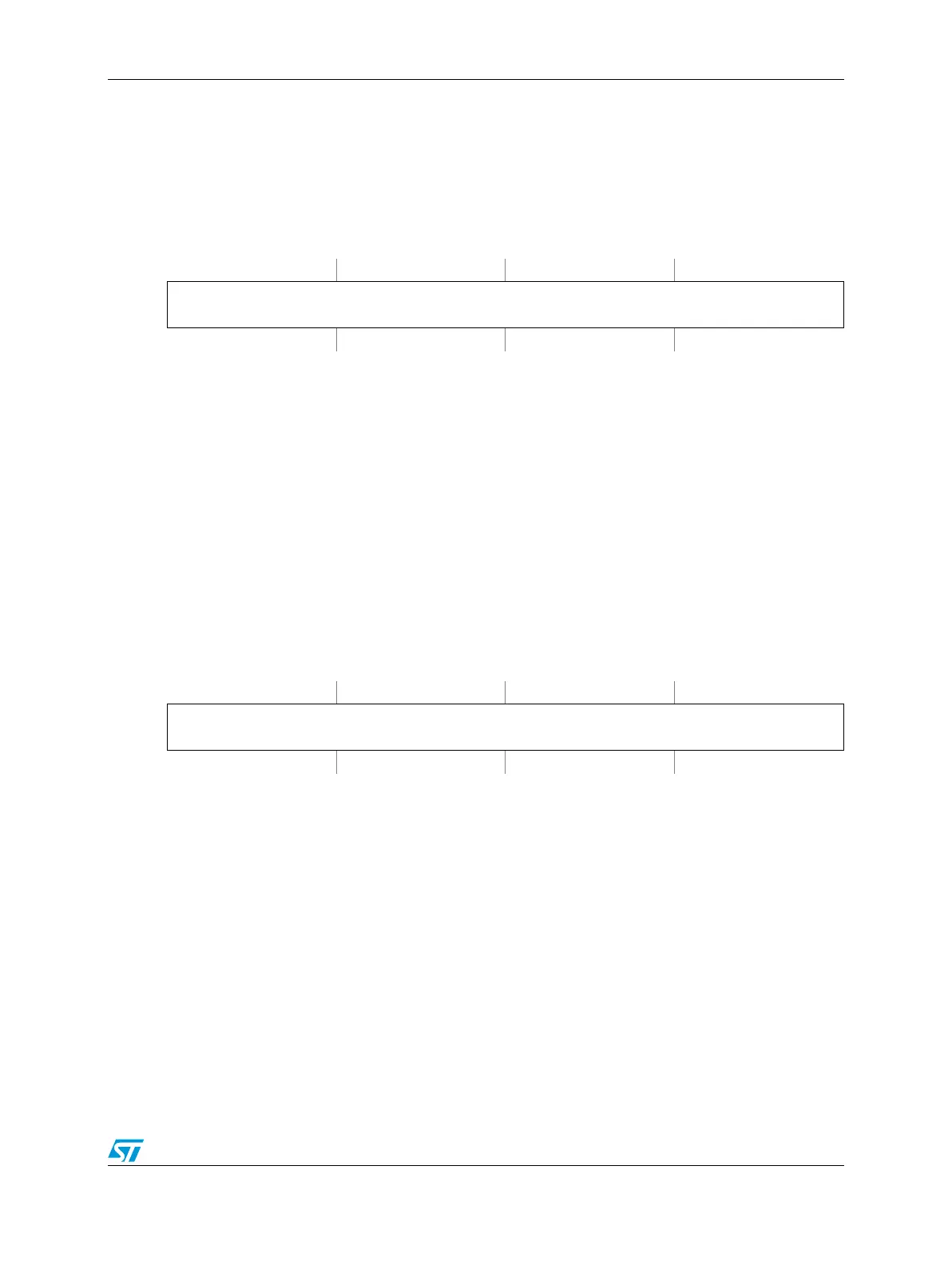
Figure 340. Value Register 1 (VAL1)
Address:
Base + 0x000A (Submodule 0)
Base + 0x005A (Submodule 1)
Base + 0x00AA (Submodule 2)
Base + 0x00FA (Submodule 3) Access: User read/write
0123456789101112131415
R
VAL1
W
Reset0000000000000000
Figure 341. Value register 2 (VAL2)
Address:
Base + 0x000C (Submodule 0)
Base + 0x005C (Submodule 1)
Base + 0x00AC (Submodule 2)
Base + 0x00FC (Submodule 3) Access: User read/write
0123456789101112131415
R
VAL2
W
Reset0000000000000000