RM0046 FlexPWM
Doc ID 16912 Rev 5 681/936
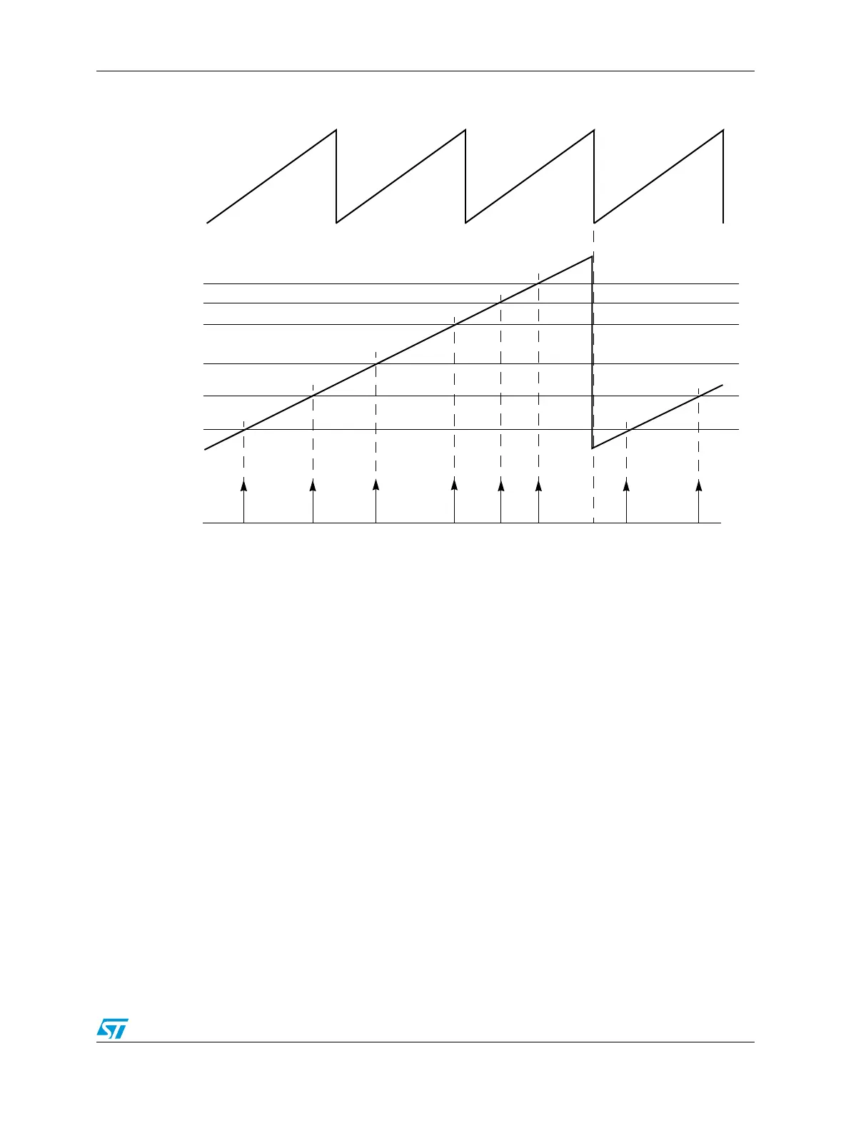
Figure 367. Multiple output triggers over several PWM cycles
25.7.6 Synchronous switching of multiple outputs
Before the PWM signals are routed to the output pins, they are processed by a hardware
block that permits all submodule outputs to be switched synchronously. This feature can be
extremely useful in commutated motor applications where the next commutation state can
be laid in ahead of time and then immediately switched to the outputs when the appropriate
condition or time is reached. Not only do all the changes occur synchronously on all
submodule outputs, but they occur IMMEDIATELY after the trigger event occurs eliminating
any interrupt latency.
The synchronous output switching is accomplished via a signal called FORCE_OUT. This
signal originates from the local FORCE bit within the submodule, from submodule 0, or from
external to the PWM module and, in most cases, is supplied from an external timer channel
configured for output compare. In a typical application, software sets up the desired states of
the output pins in preparation for the next FORCE_OUT event. This selection lays dormant
until the FORCE_OUT signal transitions and then all outputs are switched simultaneously.
The signal switching is performed upstream from the deadtime generator so that any abrupt
changes that might occur do not violate deadtime on the power stage when in
complementary mode.
Figure 368 shows a popular application that can benefit from this feature. On a brushless
DC motor it is desirable on many cases to spin the motor without need of hall-effect sensor
feedback. Instead, the back EMF of the motor phases is monitored and this information is
used to schedule the next commutation event. The top waveforms of Figure 368 are a
VAL5
VAL4
VAL3
VAL1
VAL0
Output Triggers
VAL2
Reload
Submodule 0 counter (PWM generation)
Submodule1 counter