RM0046 FlexPWM
Doc ID 16912 Rev 5 665/936
The DTCNT0 field controls the deadtime during 0 to 1 transitions of the PWMA output
(assuming normal polarity). The DTCNT1 field controls the deadtime during 0 to 1
transitions of the complementary PWMB output.
25.6.4 Configuration registers
The base address of the configuration registers is equal to the base address of the PWM
plus as offset of 0x140.
Output Enable register (OUTEN)
The relationship between the fields of OUTEN and the submodules is as follows:
● PWMx_EN[3] enables/disables submodule 3
● PWMx_EN[2] enables/disables submodule 2
● PWMx_EN[1] enables/disables submodule 1
● PWMx_EN[0] enables/disables submodule 0
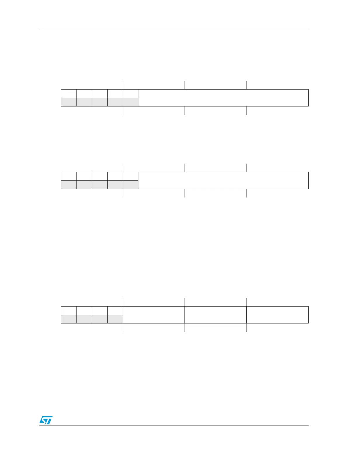
Figure 351. Deadtime Count Register 0 (DTCNT0)
Address:
Base + 0x0024 (Submodule 0)
Base + 0x0074 (Submodule 1)
Base + 0x00C4 (Submodule 2)
Base + 0x0114 (Submodule 3) Access: User read/write
0123456789101112131415
R00000
DTCNT0
W
Reset0000011111111111
Figure 352. Deadtime Count register 1 (DTCNT1)
Address:
Base + 0x0026 (Submodule 0)
Base + 0x0076 (Submodule 1)
Base + 0x00C6 (Submodule 2)
Base + 0x0116 (Submodule 3) Access: User read/write
0123456789101112131415
R00000
DTCNT1
W
Reset0000011111111111
Figure 353. Output Enable register (OUTEN)
Address:
Base + 0x0140 Access: User read/write
0123456789101112131415
R0000
PWMA_EN[3:0] PWMB_EN[3:0] PWMX_EN[3:0]
W
Reset0000000000000000