RM0046 Interrupt Controller (INTC)
Doc ID 16912 Rev 5 213/936
INTC Module Configuration Register (INTC_MCR)
The module configuration register configures options of the INTC.
INTC Current Priority Register (INTC_CPR)
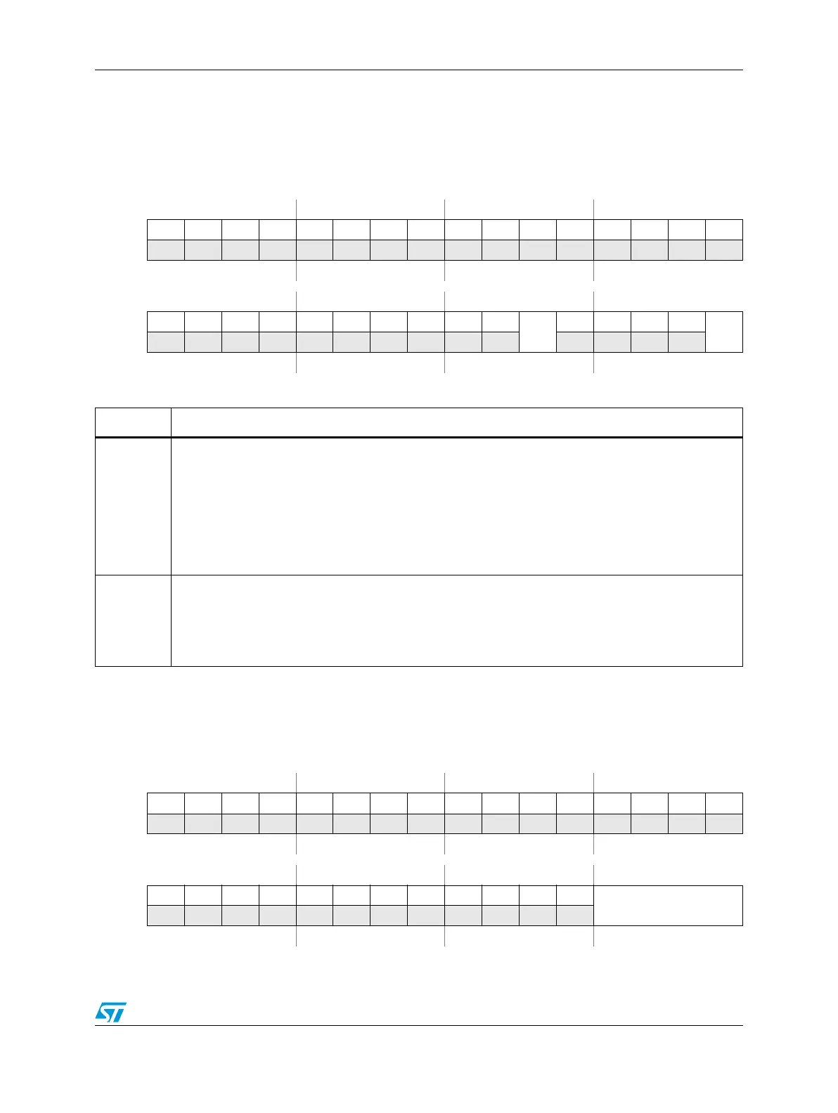
Figure 78. INTC Module Configuration Register (INTC_MCR)
Address:
Base + 0x0000 Access: User read/write
0123456789101112131415
R000000 0000000 000
W
Reset0000000000000000
16 17 18 19 20 21 22 23 24 25 26 27 28 29 30 31
R 0 0 000000 0 0
VTES
0 0 0 0
HVEN
W
Reset0000000000000000
Table 69. INTC_MCR field descriptions
Field Description
26
VTES
Vector table entry size
Controls the number of 0s to the right of INTVEC in Section , “INTC Interrupt Acknowledge
Register(INTC_IACKR). If the contents of INTC_IACKR are used as an address of an entry in a
vector table as in software vector mode, then the number of right most 0s will determine the size of
each vector table entry. VTES impacts software vector mode operation but also affects
INTC_IACKR[INTVEC] position in both hardware vector mode and software vector mode.
0 4 bytes
1 8 bytes
31
HVEN
Hardware vector enable
Controls whether the INTC is in hardware vector mode or software vector mode. Refer to Section 9.4,
“Modes of operation, for the details of the handshaking with the processor in each mode.
0 Software vector mode
1 Hardware vector mode
Figure 79. INTC Current Priority Register (INTC_CPR)
Address:
Base + 0x0008 Access: User read/write
0123456789101112131415
R000000 0000000 000
W
Reset0000000000000000
16 17 18 19 20 21 22 23 24 25 26 27 28 29 30 31
R 0 00000000000
PRI
W
Reset0000000000001111