Clock Generation Module (MC_CGM) RM0046
134/936 Doc ID 16912 Rev 5
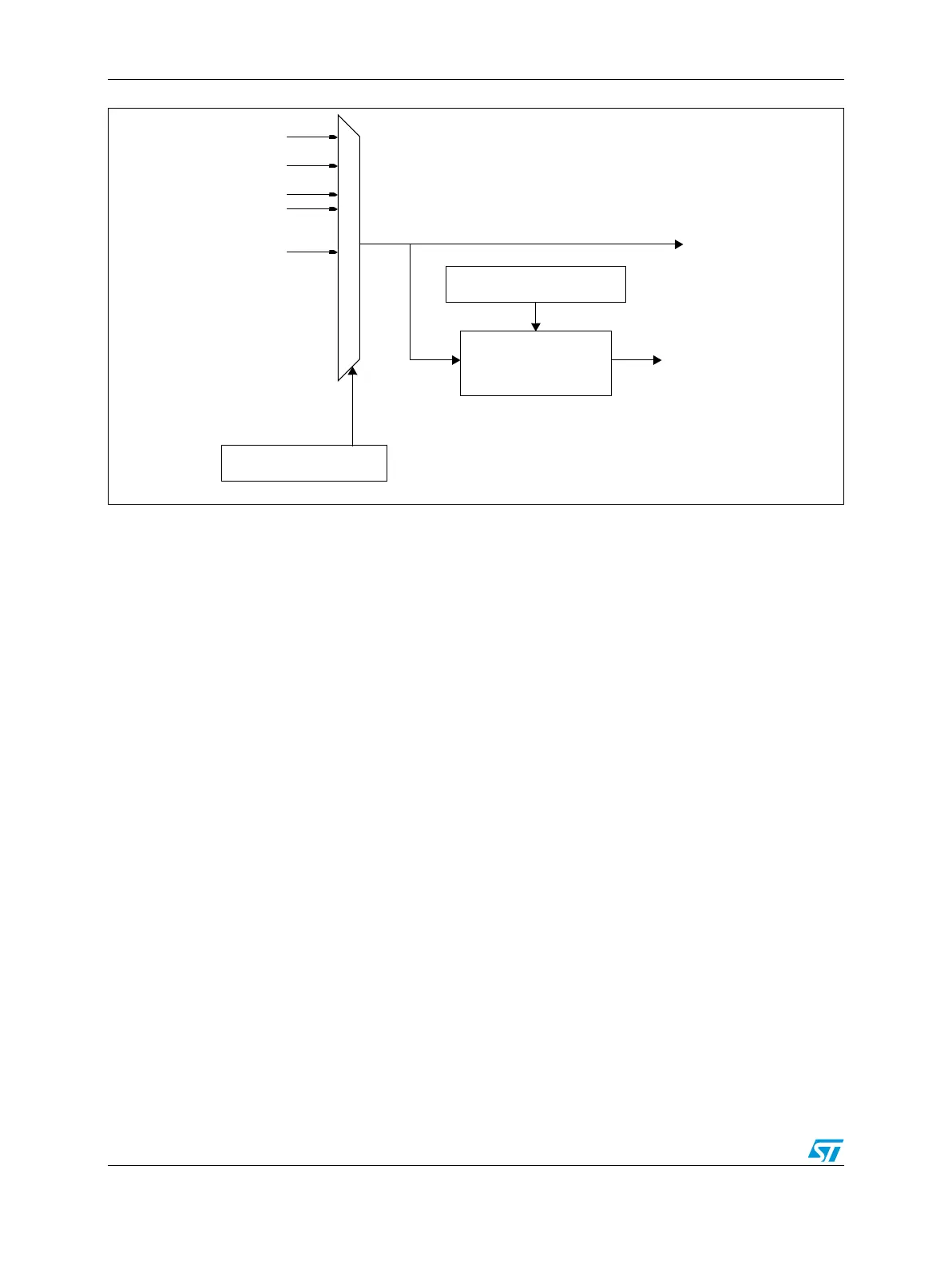
Figure 40. MC_CGM Auxiliary Clock 2 Generation Overview
5.8.1 Auxiliary Clock Source Selection
During normal operation, the auxiliary clock selection is done via the CGM_AC0…2_SC
registers. If software selects an ‘unavailable’ source, the old selection remains, and the
register content does not change.
5.8.2 Auxiliary Clock Dividers
The MC_CGM generates the following derived clocks:
● (unused) - controlled by the CGM_AC0_DC0 register
● (unused) - controlled by the CGM_AC1_DC0 register
● (unused) - controlled by the CGM_AC2_DC0 register
5.9 Dividers Functional Description
Dividers are used for the generation of divided system and peripheral clocks. The MC_CGM
has the following control registers for built-in dividers:
● Section 5.5.4, “System Clock Divider Configuration Register (CGM_SC_DC0)
● Section 5.5.6, “Auxiliary Clock 0 Divider Configuration Register (CGM_AC0_DC0)
● Section 5.5.8, “Auxiliary Clock 1 Divider Configuration Register (CGM_AC1_DC0)
● Section 5.5.10, “Auxiliary Clock 2 Divider Configuration Register (CGM_AC2_DC0)
The reset value of all counters is ‘1’. If a divider has its DE bit in the respective configuration
register set to ‘0’ (the divider is disabled), any value in its DIVn field is ignored.
CGM_AC2_DC0 Register
clock divider
(unused)
(unused)
(no clock) 2
(no clock) 4
(no clock) 5
(no clock) 8
CGM_AC2_SC Register
(no clock) 0