System Integration Unit Lite (SIUL) RM0046
252/936 Doc ID 16912 Rev 5
Note: A transfer error will be issued when trying to access completely reserved register space.
11.5.2 Register description
This section describes in address order all the SIUL registers. Each description includes a
standard register diagram. Details of register bit and field function follow the register
diagrams, in bit order. The numbering convention of register is MSB = 0, however the
numbering of internal field is LSB = 0, for example PARTNUM[5] = MIDR1[10].
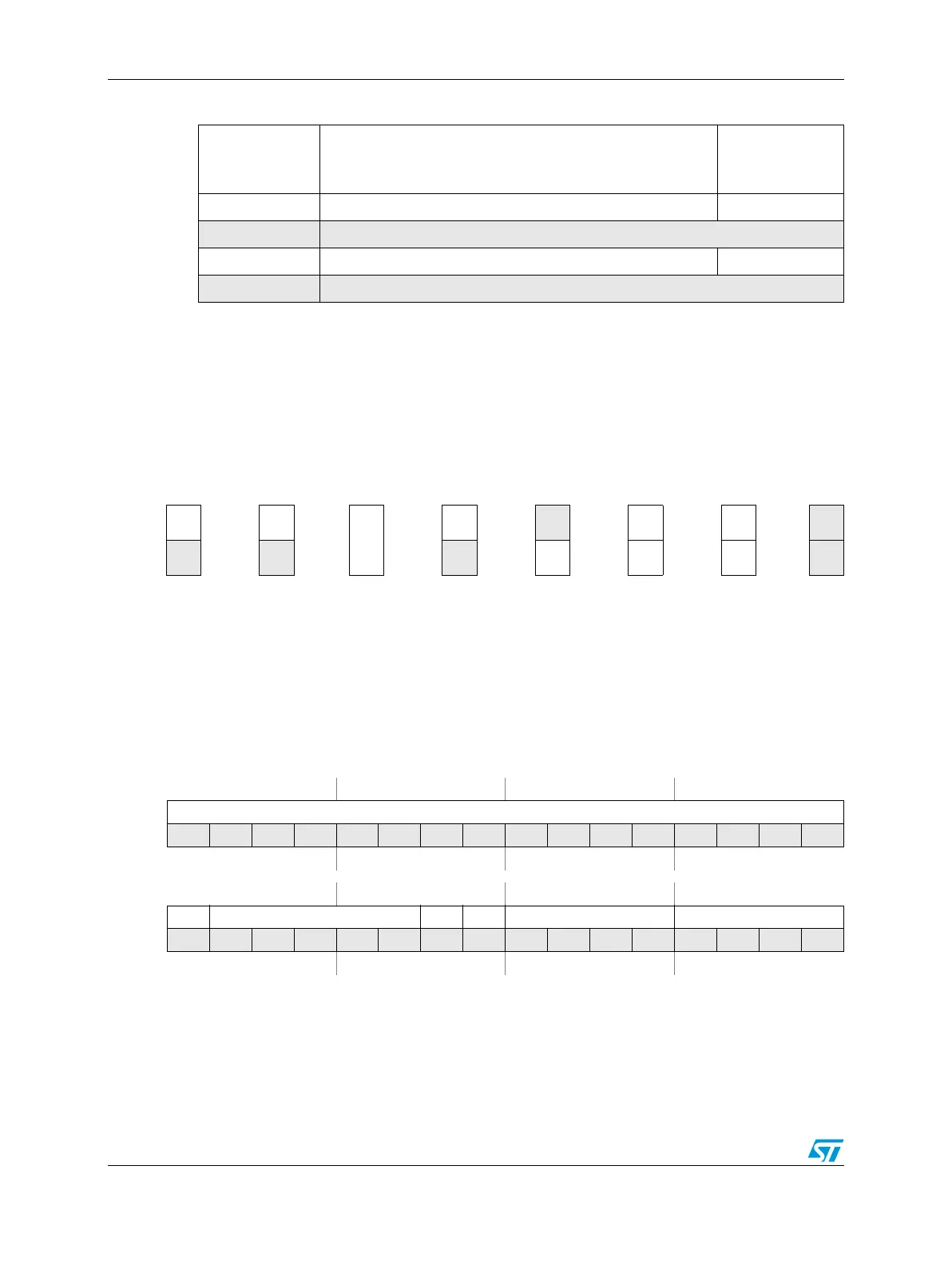
Figure 97. Key to register fields
MCU ID Register #1 (MIDR1)
This register contains the part number and the package ID of the device.
0x1000–0x
1060
Interrupt Filter Maximum Counter registers 0–24 (IFMC[0:24]) on page 11-265
0x1064–0x107C Reserved
0x1080 Interrupt Filter Clock Prescaler Register (IFCPR) on page 11-266
0x1084–0x3FFF Reserved
Table 90. SIUL memory map (continued)
Offset from
SIUL_BASE
(0xC3F9_0000)
Register Location
Always
reads 1
1
Always
reads 0
0
R/W bit BIT
Read-
only bit
BIT
Write-
only bit
Write 1
to clear
BIT
Self-
clear bit
0
N/A
BIT w1c BIT
Figure 98. MCU ID Register #1 (MIDR1)
Address:
Base + 0x0004 Access: User read-only
0123456789101112131415
R PARTNUM[15:0]
W
Reset0101011000000010
16 17 18 19 20 21 22 23 24 25 26 27 28 29 30 31
R CSP PKG[4:0] 0 0 MAJOR_MASK[3:0]
(1)
MINOR_MASK[3:0]
1
W
Reset0010010000000000
1. See Table 91.