Cyclic Redundancy Check (CRC) RM0046
804/936 Doc ID 16912 Rev 5
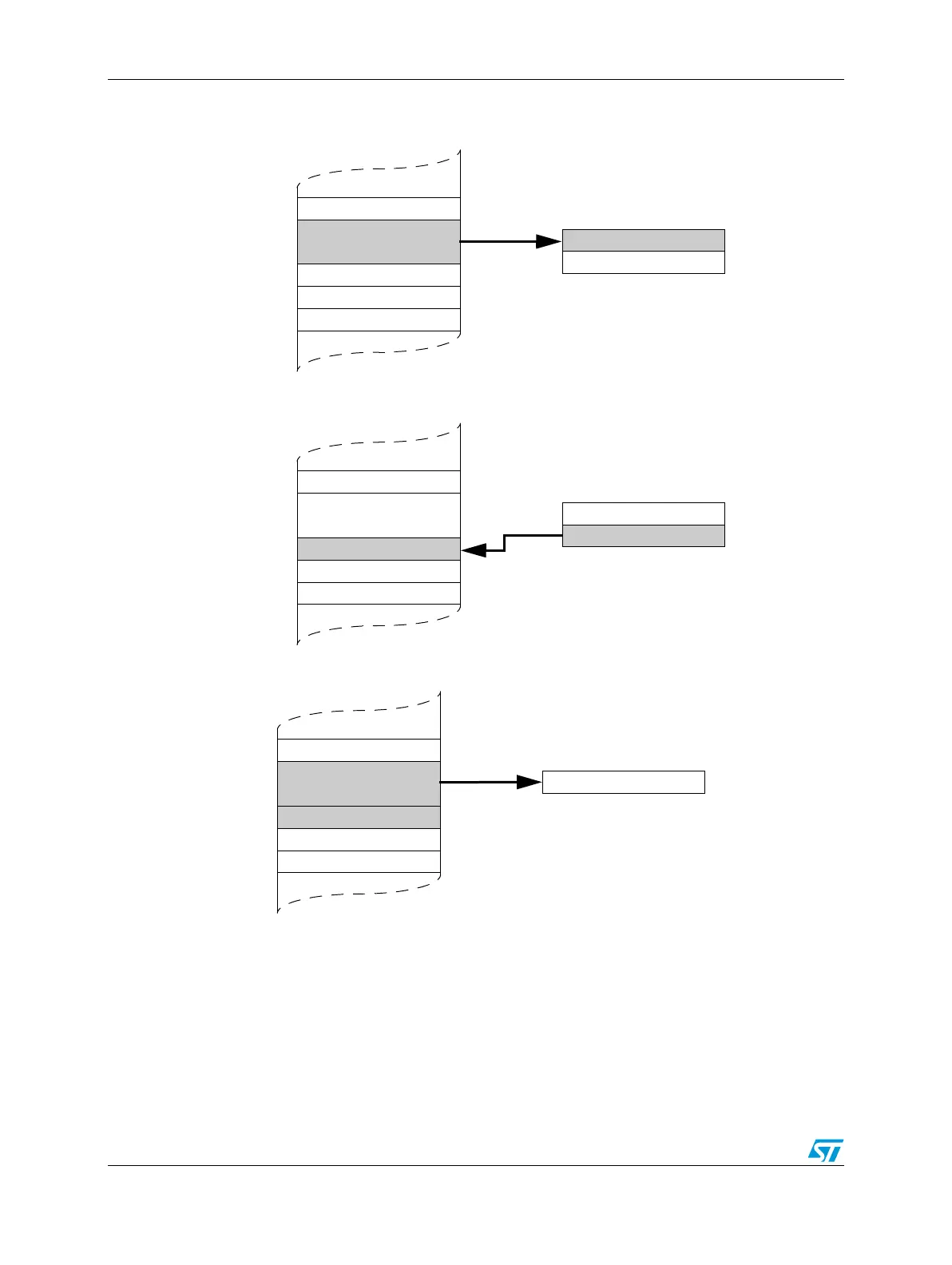
Figure 477. DMA-CRC Transmission Sequence
The following sequence, as given in Figure 478, shall be applied to manage the reception
data flow:
● DMA/CRC module configuration (context x, channel x) by CPU
● Data block (payload + CRC) transfer from the PERIPH (e.g., SPI Rx fifo) module to the
MEM (phase 1) by DMA (periph2mem data transfer, channel x)
CRC_OUTP
CRC_INP
Memory
CRC (context x)
CPU
Transmission Phase 2
CRC_OUTP
CRC_INP
Memory
CRC (context x)
DMA
Transmission Phase 1
CRC Checksum
Tx FIFO
Memory
SPI
DMA
Transmission Phase 3
CRC Checksum
Payload
(mem2mem
channel x)
(mem2periph
channel x)
Payload
Payload