RM0046 Deserial Serial Peripheral Interface (DSPI)
Doc ID 16912 Rev 5 457/936
Note: TXDATA is used in master and slave modes.
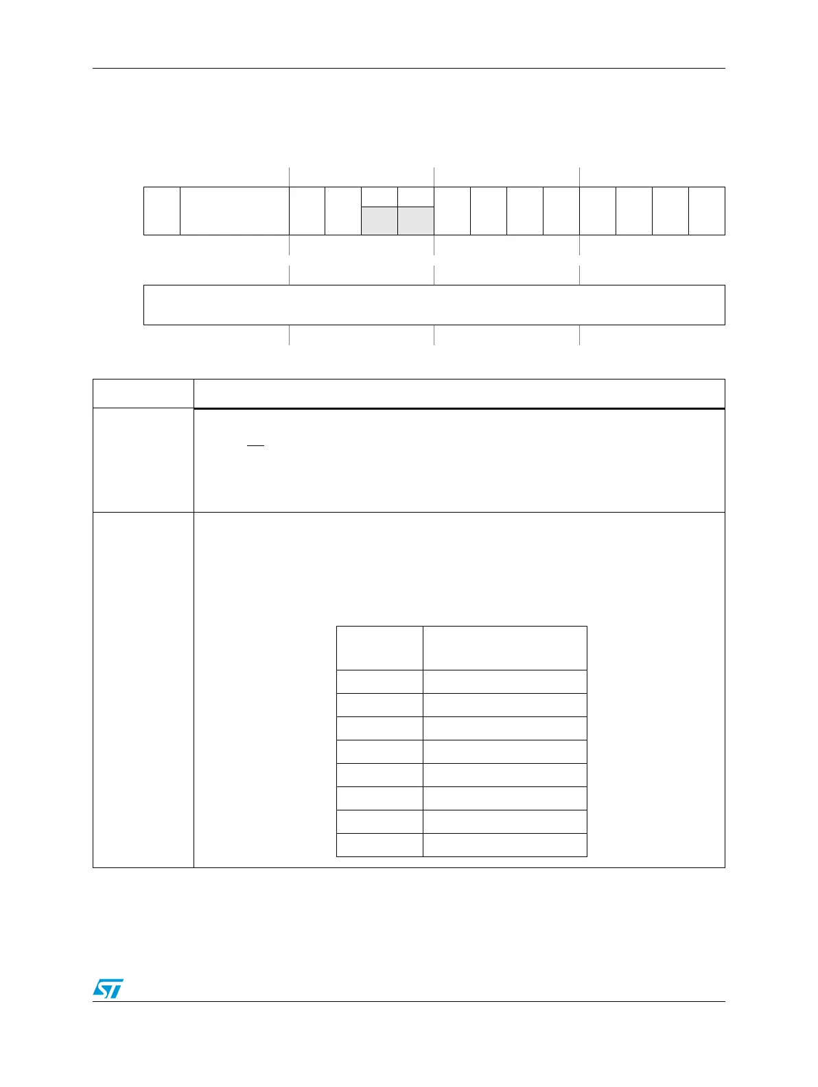
Figure 212. DSPI PUSH TX FIFO Register (DSPIx_PUSHR)
Address Base + 0x0034 Access: User read/write
0123456789101112131415
R
CONT
CTAS EOQ
CTCNT
00
PCS7
PCS6
PCS5
PCS4
PCS3
PCS2
PCS1
PCS0
W
Reset0000000000000000
16 17 18 19 20 21 22 23 24 25 26 27 28 29 30 31
R
TXDATA
W
Reset0000000000000000
Table 217. DSPIx_PUSHR field descriptions
Field Description
0
CONT
Continuous peripheral chip select enable
Selects a continuous selection format. The bit is used in SPI master mode. The bit enables the
selected CS
signals to remain asserted between transfers. Refer to Section , “Continuous
selection format for more information.
0 Return peripheral chip select signals to their inactive state between transfers.
1 Keep peripheral chip select signals asserted between transfers.
1–3
CTAS
[0:2]
Clock and transfer attributes select
Selects which of the DSPIx_CTARs sets the transfer attributes for the SPI frame. In SPI slave
mode, DSPIx_CTAR0 is used. The following table shows how the CTAS values map to the
DSPIx_CTARs. There are eight DSPIx_CTARs in the device DSPI implementation.
Use in SPI master mode only.
CTAS
Use Clock and Transfer
Attributes from
000 DSPIx_CTAR0
001 DSPIx_CTAR1
010 DSPIx_CTAR2
011 DSPIx_CTAR3
100 DSPIx_CTAR4
101 DSPIx_CTAR5
110 DSPIx_CTAR6
111 DSPIx_CTAR7