RM0046 Nexus Development Interface (NDI)
Doc ID 16912 Rev 5 889/936
controller. By using public instructions, the external hardware debugger can freeze or halt
the CPU, read and write internal state, and resume normal execution. The core does not
contain IEEE 1149.1 standard boundary cells on its interface, as it is a building block for
further integration. It does not support the JTAG related boundary scan instruction
functionality, although JTAG public instructions may be decoded and signaled to external
logic.
The OnCE logic provides for Nexus Class 1 static debug capability (utilizing the same set of
resources available to software while in internal debug mode), and is present in all e200z0h-
based designs. The OnCE module also provides support for directly integrating a Nexus
class 2 or class 3 Real-Time Debug unit with the e200z0h core for development of real-time
systems where traditional static debug is insufficient. The partitioning between a OnCE
module and a connected Nexus module to provide real-time debug allows for capability and
cost trade-offs to be made.
The e200z0h core is designed to be a fully integratable module. The OnCE TAP controller
and associated enabling logic are designed to allow concatenation with an existing JTAG
controller if present in the system. Thus, the e200z0h module can be easily integrated with
existing JTAG designs or as a stand-alone controller.
In order to enable full OnCE operation, the jd_enable_once input signal must be asserted.
In some system integrations, this is automatic, since the input will be tied asserted. Other
integrations may require the execution of the Enable OnCE command via the TAP and
appropriate entry of serial data. Exact requirements will be documented by the integrated
product specification. The jd_enable_once input signal should not change state during a
debug session, or undefined activity may occur.
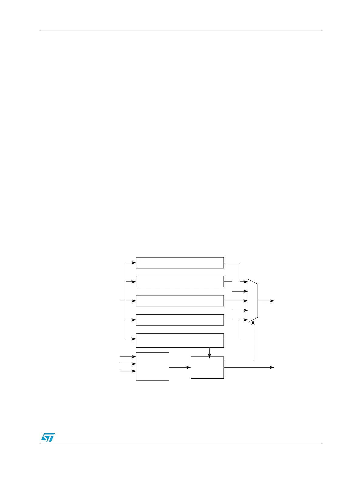
The following figures show the TAP controller state model and the TAP registers
implemented by the OnCE logic.
Figure 513. OnCE TAP Controller and Registers
The OnCE controller is implemented as a 16-state FSM (finite state machine), with a one-to-
one correspondence to the states defined for the JTAG TAP controller.
OnCE mapped Debug registers
Auxiliary data registers
External Data registers
Bypass register
TAP instruction register
TAP
controller
j_trst_b
j_tclk
j_tms
TDO
mux logic
j_tdi j_tdo
j_tdo_en
(OnCE OCMD)