eTimer RM0046
710/936 Doc ID 16912 Rev 5
26.6.2 Timer channel registers
These registers are repeated for each timer channel. The base address of channel 0 is the
same as the base address of the eTimer module as a whole. The base address of channel 1
is 0x20. This is the base address of the eTimer module plus an offset based on the number
of bytes of registers in a timer channel. The base address of each subsequent timer channel
is equal to the base address of the previous channel plus this same offset of 0x20.
Compare register 1 (COMP1)
The COMP1 register stores the value used for comparison with the counter value. More
explanation on the use of COMP1 can be found in Section , “Usage of compare registers.
0x00BA CMPLD2—Comparator Load Register 2 on page 26-722
0x00BC CCCTRL—Compare and Capture Control Register on page 26-723
0x00BE FILT—Input Filter Register on page 26-725
0x00C0–0x00FF Reserved
0x0100 WDTOL—Watchdog Time-out Low Register on page 26-726
0x0102 WDTOH—Watchdog Time-out High Register on page 26-726
0x0104–0x010B Reserved
Watchdog and Configuration registers
0x010C ENBL—Channel Enable Register on page 26-726
0x0110 DREQ0—DMA Request 0 Select Register on page 26-727
0x0112 DREQ1—DMA Request 1 Select Register on page 26-727
0x0114–0x3FFF Reserved
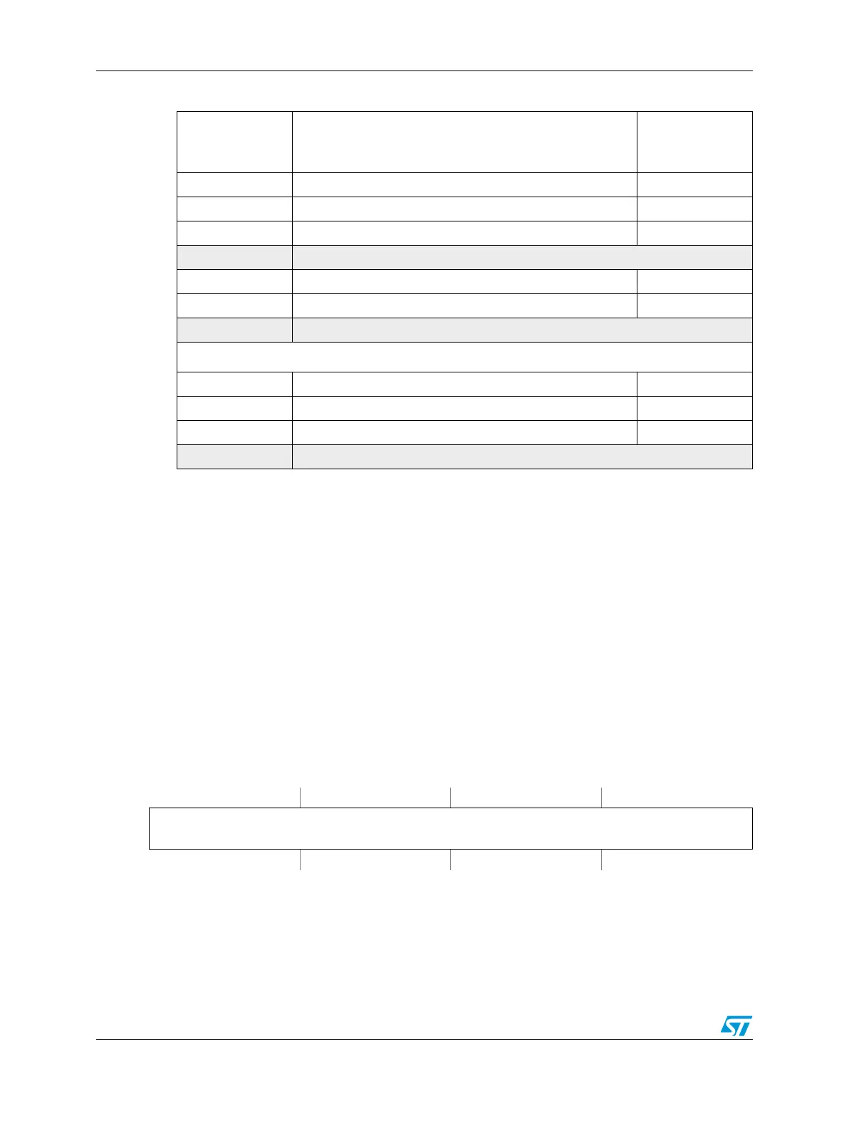
Table 364. eTimer memory map (continued)
Offset from
eTIMER0_BASE
(FFE1_8000)
Register Location
Figure 392. Compare register 1 (COMP1)
Address:
Base + 0x0000 (eTimer0)
Base + 0x0020 (eTimer1)
Base + 0x0040 (eTimer2)
Base + 0x0060 (eTimer3)
Base + 0x0080 (eTimer4)
Base + 0x00A0 (eTimer5)
Access: User read/write
0123456789101112131415
R
COMP1[15:0]
W
Reset0000000000000000