RM0046 Deserial Serial Peripheral Interface (DSPI)
Doc ID 16912 Rev 5 437/936
20 Deserial Serial Peripheral Interface (DSPI)
20.1 Introduction
This chapter describes the deserial serial peripheral interface (DSPI), which provides a
synchronous serial bus for communication between the MCU and an external peripheral
device.
The SPC560P40/34 implements the modules DSPI0, 1 and 2. The “x” appended to signal
names signifies the module to which the signal applies. Thus CS0_x specifies that the CS0
signal applies to DSPI module 0, 1, etc.
20.2 Block diagram
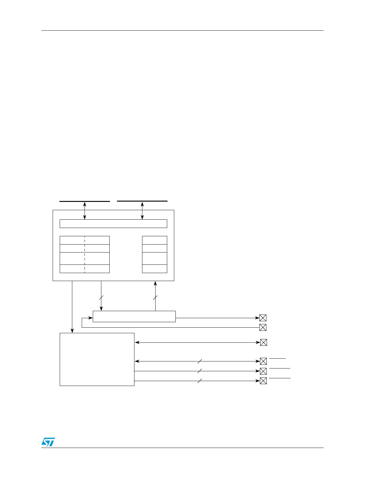
A block diagram of the DSPI is shown in Figure 205.
Figure 205. DSPI block diagram
CMD
DMA and interrupt control
TX FIFO RX FIFO
TX data RX data
16 16
Shift register
SOUT_x (x =0:2)
SPI
SPI baud rate,
delay and transfer
control
SIN_x (x =0:2)
SCK_x (x =0:2)
CS4:7_0
INTCeDMA
4
CS0_x (x =0:2)
1
DSPI_x (x =0:2)
DSPI_0
CS1:3_x (x =0:2)
3
DSPI_x (x =0:2)