FlexPWM RM0046
678/936 Doc ID 16912 Rev 5
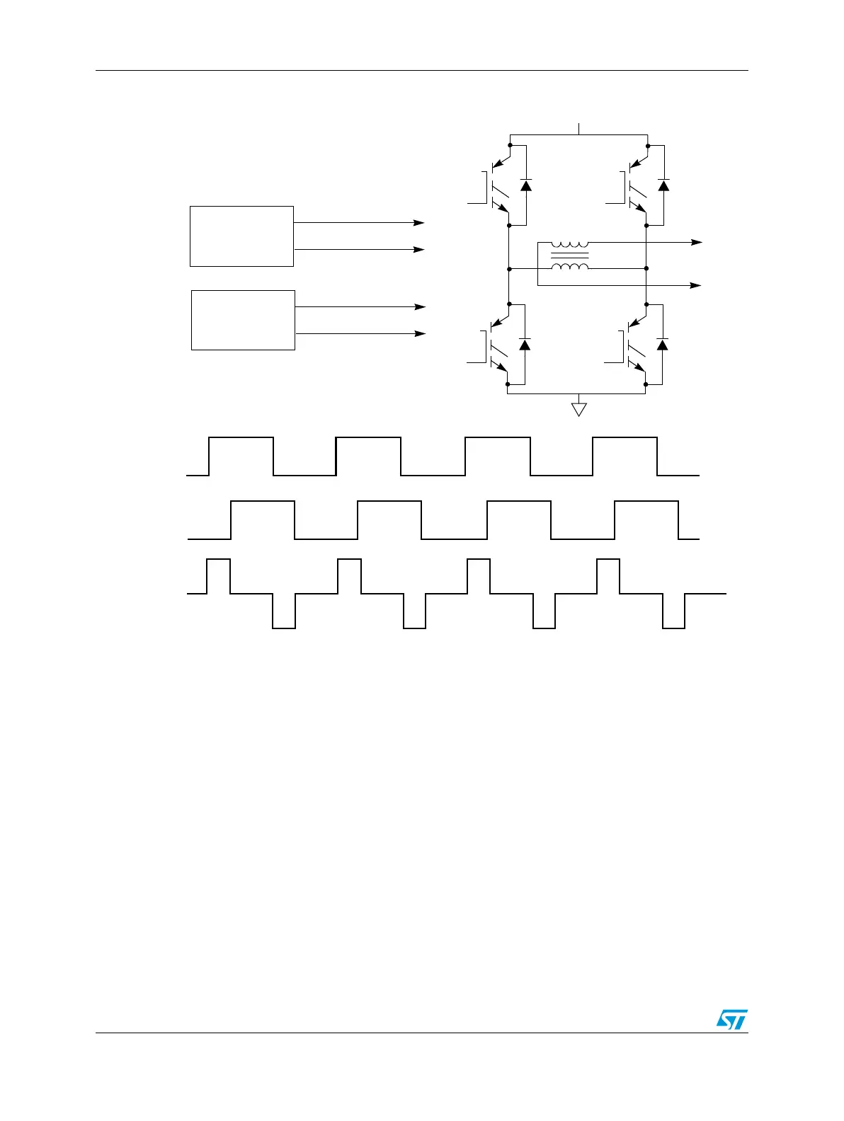
Figure 364. Phase-shifted PWMs applied to a transformer primary
25.7.4 Double switching PWMs
Double switching PWM output is supported to aid in single shunt current measurement and
three phase reconstruction. This method support two independent rising edges and two
independent falling edges per PWM cycle. The VAL2 and VAL3 registers generate the even
channel (labeled as PWMA in the figure) while VAL4 and VAL5 generate the odd channel.
The two channels are combined using XOR logic (see Figure 373) as shown in Figure 365.
The DBLPWM signal can be run through the deadtime insertion logic.
Top Left
Bottom Left
Submodule 0
Top Right
Bottom Right
Submodule 1
V+
Left Side
Right Side
Transformer