Functional Safety RM0046
742/936 Doc ID 16912 Rev 5
Note: The GCR[UAA] bit has no effect on the allowed access modes for the registers in the
Register protection module.
27.2.6 Functional description
General
This module provides a generic register (address) write-protection mechanism. The
protection size can be:
● 32-bit (address == multiples of 4)
● 16-bit (address == multiples of 2)
● 8-bit (address == multiples of 1)
● unprotected (address == multiples of 1)
For all addresses that are protected there are SLBRn[SLBm] bits that specify whether the
address is locked. When an address is locked it can only be read but not written in any
mode (supervisor/normal). If an address is unprotected the corresponding SLBRn[SLBm] bit
is always 0b0 no matter what software is writing to.
Change lock settings
To change the setting whether an address is locked or unlocked, the corresponding
SLBRn[SLBm] bit needs to be changed. This can be done using the following methods:
● Modify the SLBRn[SLBm] bit directly by writing to area #4
● Set the SLBRn[SLBm] bit(s) by writing to the mirror module space (area #3)
Both methods are explained in the following sections.
Change lock settings directly via area #4
In memory area #4 the lock bits are located. They can be modified by writing to them. Each
SLBRn[SLBm] bit has a corresponding SLBRn[WEm] mask bit, which protects it from being
modified. This masking makes clear-modify-write operations unnecessary.
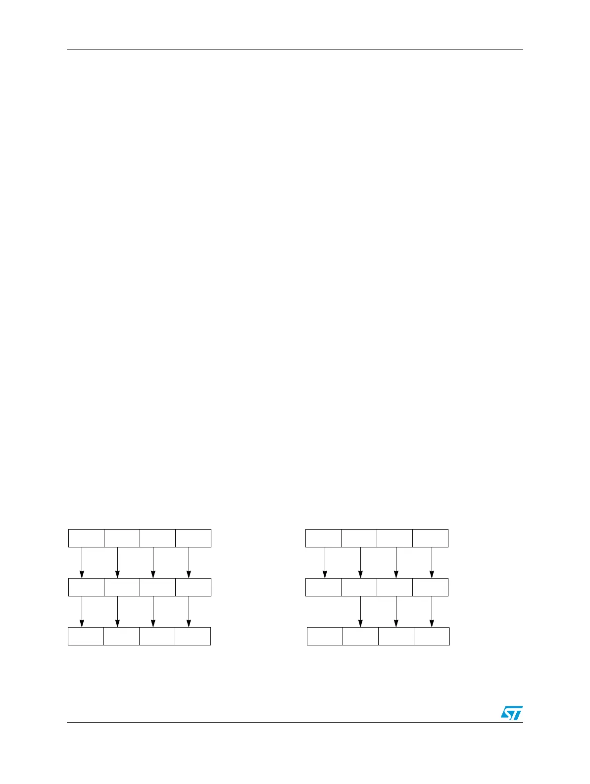
Figure 422 shows two modification examples. In the left example there is a write access to
the SLBRn register specifying a mask value that allows modification of all SLBRn[SLBm]
bits. The example on the right specifies a mask that only allows modification of the bits
SLBRn[SLB[3:1]].
Figure 422. Change lock settings directly via area #4
1
SLB3SLB2SLB1SLB0
SLBRn[WE[3:0]]
SLBRn[SLB[3:0]]
SLB3SLB2SLB1SLB0
SLBRn[SLB[3:0]]
change allowed
to SLB3
write data
to SLB2to SLB1to SLB0
111
1SLBRn[WE[3:0]]
to SLB3
write data
to SLB2to SLB1to SLB0
110
change allowed