Interrupt Controller (INTC) RM0046
210/936 Doc ID 16912 Rev 5
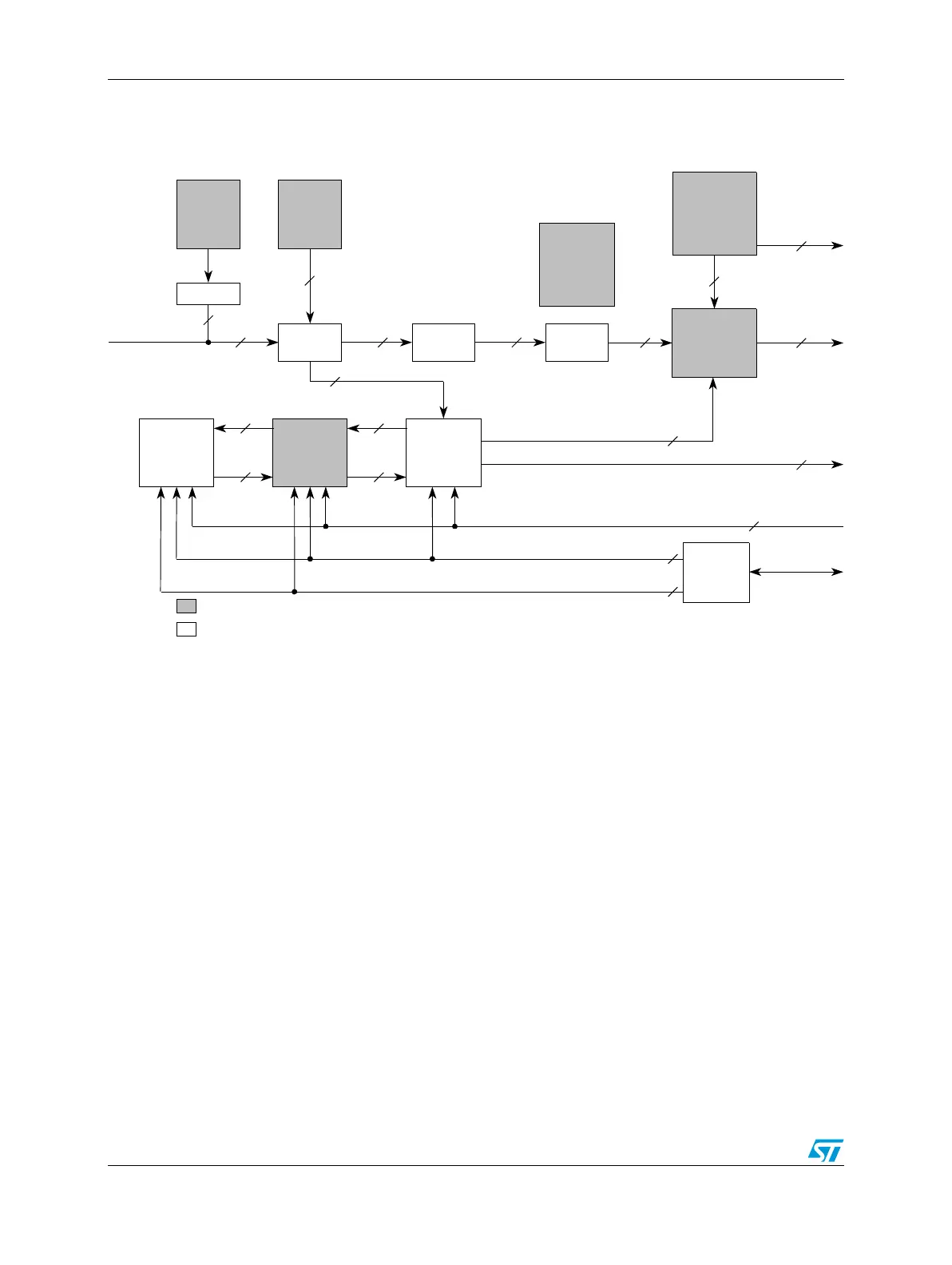
9.3 Block diagram
Figure 77 shows a block diagram of the interrupt controller (INTC).
Figure 77. INTC block diagram
9.4 Modes of operation
9.4.1 Normal mode
In normal mode, the INTC has two handshaking modes with the processor: software vector
mode and hardware vector mode.
Note: To correctly configure the interrupts in both software and hardware vector mode, the user
must also configure the IVPR. The core register IVPR contains the base address for the
interrupt handlers. Please refer to the core reference manual for more information.
Software vector mode
In software vector mode, the interrupt exception handler software must read a register in the
INTC to obtain the vector associated with the interrupt request to the processor. The INTC
will use software vector mode for a given processor when its associated HVEN bit in
INTC_MCR is negated. The hardware vector enable signal to processor 0 or processor 1 is
driven as negated when its associated HVEN bit is negated. The vector is read from
Hardware
Vector Enable
Software
Set/Clear
Interrupt
Registers
Flag Bits
Peripheral
Interrupt
Requests
Module
Configuration
Register
Highest Priority
4
Priority
Comparator
Slave
Interface
for Reads
& Writes
1
Push/Update/Acknowledge
1
1
1
Update Interrupt Vector
1
Interrupt
Request to
Processor
Memory Mapped Registers
Non-Memory Mapped Logic
End of
Interrupt
Register
Request
Selector
Priority
Arbitrator
Highest
Priority
Interrupt
Requests
n
1
n
1
Vector
Encoder
Interrupt
Vector
9
Processor 0
Interrupt
Acknowledge
Register
Interrupt
Vector
9
n
1
8
n
1
x
4-bits
New
Priority
4
Current
Priority
4
Processor 0
Current
Priority
Register
Processor 0
Priority
LIFO
Pop
1
Lowest
Vector
Interrupt
Request
1
Vector Table
Entry Size
Pushed
Priority
4
Popped
Priority
4
Interrupt Acknowledge
1. The total number of interrupt sources is 128, which includes 16 reserved sources and 8 software sources.
Priority
Select
Registers