RM0046 FlexPWM
Doc ID 16912 Rev 5 675/936
25.7 Functional description
25.7.1 Center-aligned PWMs
Each submodule has its own timer that is capable of generating PWM signals on two output
pins. The edges of each of these signals are controlled independently as shown in
Figure 361.
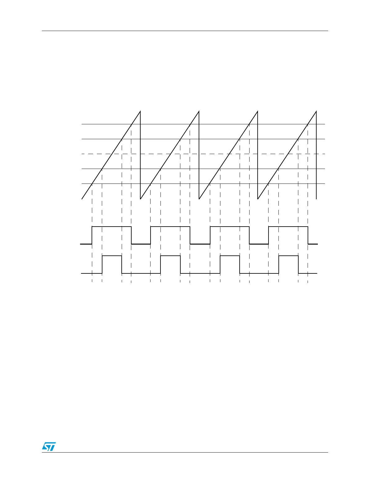
Figure 361. Center-aligned example
The submodule timers only count in the up direction and then reset to the INIT value.
Instead of having a single value that determines pulse width, there are two values that must
be specified: the turn on edge and the turn off edge. This double action edge generation not
only gives the user control over the pulse width, but over the relative alignment of the signal
as well. As a result, there is no need to support separate PWM alignment modes since the
PWM alignment mode is inherently a function of the turn on and turn off edge values.
Figure 361 also illustrates an additional enhancement to the PWM generation process.
When the counter resets, it is reloaded with a user-specified value, which may or may not be
zero. If the value chosen happens to be the 2’s complement of the modulus value, then the
PWM generator operates in “signed” mode. This means that if each PWM’s turn on and turn
off edge values are also the same number but only different in their sign, the “on” portion of
the output signal will be centered around a count value of zero. Therefore, only one PWM
value needs to be calculated in software and then this value and its negative are provided to
the submodule as the turn off and turn on edges respectively. This technique will result in a
pulse width that always consists of an odd number of timer counts. If all PWM signal edge
calculations follow this same convention, then the signals will be center-aligned with respect
VAL1 (0x0100)
VAL3
VAL5
VAL0 (0x0000)
VAL4
VAL2
INIT (0xFF00)
PWMA
PWMB