Periodic Interrupt Timer (PIT) RM0046
784/936 Doc ID 16912 Rev 5
Timer Load Value Register n (LDVALn)
These registers select the timeout period for the timer interrupts.
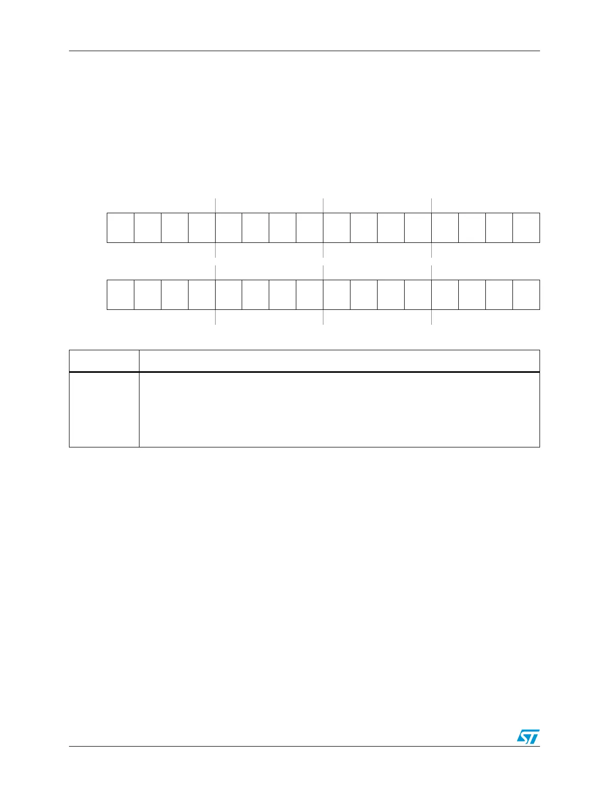
Figure 458. Timer Load Value Register n (LDVALn)
Address:
Channel Base + 0x0000
LDVAL0 = PIT_BASE + 0x0100
LDVAL1 = PIT_BASE + 0x0110
LDVAL2 = PIT_BASE + 0x0120
LDVAL3 = PIT_BASE + 0x0130
Access: User read/write
0123456789101112131415
R
TSV
31
TSV
30
TSV
29
TSV
28
TSV
27
TSV
26
TSV
25
TSV
24
TSV
23
TSV
22
TSV
21
TSV
20
TSV
19
TSV
18
TSV
17
TSV
16
W
Reset0000000000000000
16 17 18 19 20 21 22 23 24 25 26 27 28 29 30 31
R
TSV
15
TSV
14
TSV
13
TSV
12
TSV
11
TSV
10
TSV
9
TSV
8
TSV7 TSV6 TSV5 TSV4 TSV3 TSV2 TSV1 TSV0
W
Reset0000000000000000
Table 419. LDVALn field descriptions
Field Description
TSVn
Time Start Value Bits
These bits set the timer start value. The timer will count down until it reaches 0, then it will
generate an interrupt and load this register value again. Writing a new value to this register will not
restart the timer, instead the value will be loaded once the timer expires. To abort the current cycle
and start a timer period with the new value, the timer must be disabled and enabled again (see
Figure 463).