RM0046 LIN Controller (LINFlex)
Doc ID 16912 Rev 5 527/936
measurement, the LINFlex state machine is stopped and no data is transferred to the data
register.
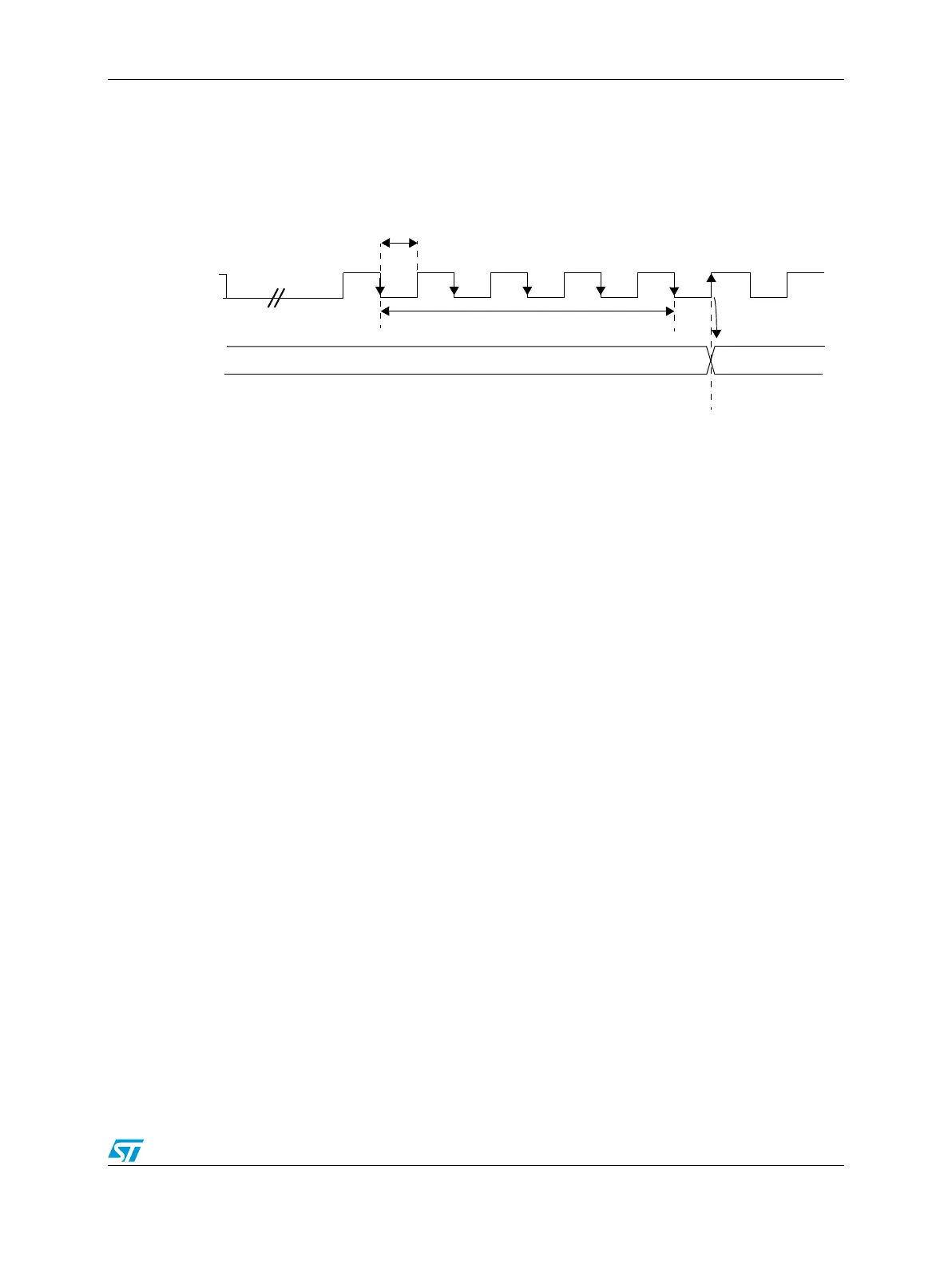
Figure 260. LIN synch field measurement
LFDIV is an unsigned fixed point number. The mantissa is coded on 12 bits in the LINIBRR
and the fraction is coded on 4 bits in the LINFBRR.
If LASE bit = 1 then LFDIV is automatically updated at the end of each LIN Synch Field.
Three internal registers (not user-accessible) manage the auto-update of the LINFlex divider
(LFDIV):
● LFDIV_NOM (nominal value written by software at LINIBRR and LINFBRR addresses)
● LFDIV_MEAS (results of the Field Synch measurement)
● LFDIV (used to generate the local baud rate)
On transition to idle, break or break delimiter state due to any error or on reception of a
complete frame, hardware reloads LFDIV with LFDIV_NOM.
Deviation error on the Synch Field
The deviation error is checked by comparing the current baud rate (relative to the slave
oscillator) with the received LIN Synch Field (relative to the master oscillator). Two checks
are performed in parallel.
The first check is based on a measurement between the first falling edge and the last falling
edge of the Synch Field:
● If D1 > 14.84%, LHE is set.
● If D1 < 14.06%, LHE is not set.
● If 14.06% < D1 < 14.84%, LHE can be either set or reset depending on the dephasing
between the signal on LINFlex_RX pin the f
periph_set_1_clk
clock.
The second check is based on a measurement of time between each falling edge of the
Synch Field:
● If D2 > 18.75%, LHE is set.
● If D2 < 15.62%, LHE is not set.
● If 15.62% < D2 < 18.75%, LHE can be either set or reset depending on the dephasing
between the signal on LINFlex_RX pin the f
periph_set_1_clk
clock.
LIN Break
Break
Bit0
Bit1
Bit2
Bit3
Bit4
Bit5
Bit6
Bit7
Start
Bit
Stop
Bit
Next
Start
Bit
LIN Synch Field
Measurement = 8.T
BR
=SM.T
periph_set_1_clk
LFDIV(n)
LFDIV(n+1)
LFDIV = T
BR
/ (16.T
periph_set_1_clk
) = Rounding (SM / 128)
T
periph_set_1_clk
= Clock period
T
BR
= baud rate period
T
BR
T
BR
= 16.LFDIV.T
periph_set_1_clk
SM = Synch Measurement Register (19 bits)
delim.