Deserial Serial Peripheral Interface (DSPI) RM0046
466/936 Doc ID 16912 Rev 5
DSPIx_RXFR0. For example, POPNXTPTR equal to two means that the DSPIx_RXFR2
contains the received SPI data that is returned when DSPIx_POPR is read. The
POPNXTPTR field is incremented every time the DSPIx_POPR is read. POPNXTPTR rolls
over every four frames on the MCU.
Filling the RX FIFO
The RX FIFO is filled with the received SPI data from the shift register. While the RX FIFO is
not full, SPI frames from the shift register are transferred to the RX FIFO. Every time an SPI
frame is transferred to the RX FIFO the RX FIFO counter is incremented by one.
If the RX FIFO and shift register are full and a transfer is initiated, the RFOF bit in the
DSPIx_SR is set indicating an overflow condition. Depending on the state of the ROOE bit in
the DSPIx_MCR, the data from the transfer that generated the overflow is ignored or put in
the shift register. If the ROOE bit is set, the incoming data is put in the shift register. If the
ROOE bit is cleared, the incoming data is ignored.
Draining the RX FIFO
Host software or the eDMA can remove (pop) entries from the RX FIFO by reading the
DSPIx_POPR. A read of the DSPIx_POPR decrements the RX FIFO counter by one.
Attempts to pop data from an empty RX FIFO are ignored, the RX FIFO counter remains
unchanged. The data returned from reading an empty RX FIFO is undetermined.
Refer to Section , “DSPI POP RX FIFO Register (DSPIx_POPR) for more information on
DSPIx_POPR.
When the RX FIFO is not empty, the RX FIFO drain flag (RFDF) in the DSPIx_SR is set. The
RFDF bit is cleared when the RX_FIFO is empty and the eDMA controller indicates that a
read from DSPIx_POPR is complete; alternatively the RFDF bit can be cleared by the host
writing a 1 to it.
20.8.4 DSPI baud rate and clock delay generation
The SCK_x frequency and the delay values for serial transfer are generated by dividing the
system clock frequency by a prescaler and a scaler with the option of doubling the baud
rate.
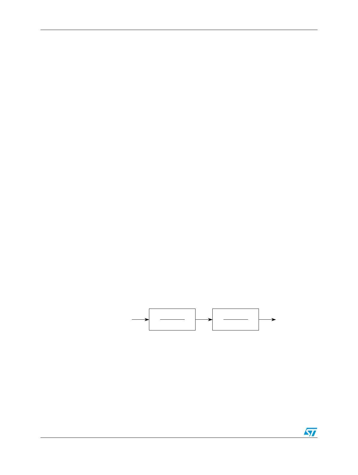
Figure 218 shows conceptually how the SCK signal is generated.
Figure 218. Communications clock prescalers and scalers
Baud rate generator
The baud rate is the frequency of the serial communication clock (SCK_x). The system
clock is divided by a baud rate prescaler (defined by DSPIx_CTAR[PBR]) and baud rate
scaler (defined by DSPIx_CTAR[BR]) to produce SCK_x with the possibility of doubling the
baud rate. The DBR, PBR, and BR fields in the DSPIx_CTARs select the frequency of
SCK_x using the following formula:
Prescaler
1
Scaler
1 + DBR
System Clock SCK_x