RM0046 Interrupt Controller (INTC)
Doc ID 16912 Rev 5 217/936
The software set/clear interrupt registers support the setting or clearing of software
configurable interrupt request. These registers contain eight independent sets of bits to set
and clear a corresponding flag bit by software. Excepting being set by software, this flag bit
behaves the same as a flag bit set within a peripheral. This flag bit generates an interrupt
request within the INTC like a peripheral interrupt request. Writing a ‘1’ to SETx will leave
SETx unchanged at 0 but sets CLRx. Writing a ‘0’ to SETx has no effect. CLRx is the flag
bit. Writing a ‘1’ to CLRx clears it. Writing a ‘0’ to CLRx has no effect. If a ‘1’ is written
simultaneously to a pair of SETx and CLRx bits, CLRx will be asserted, regardless of
whether CLRx was asserted before the write.
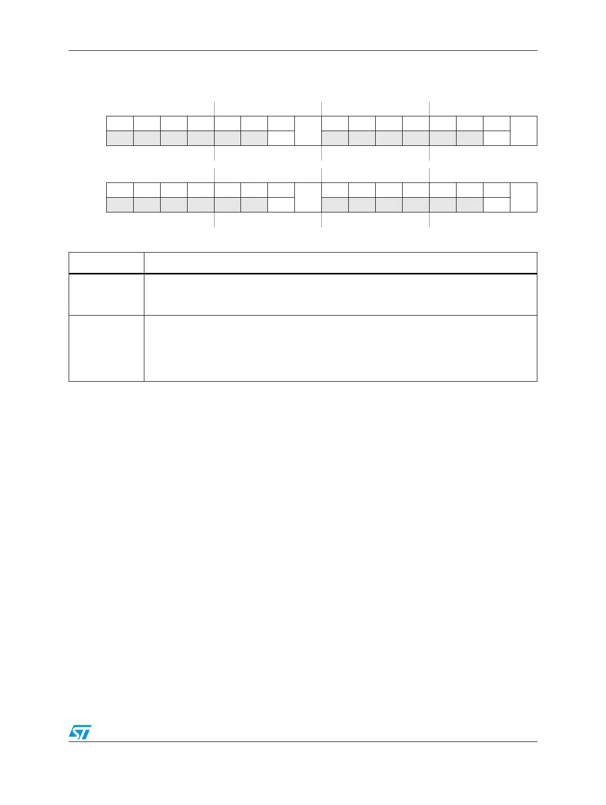
Figure 83. INTC Software Set/Clear Interrupt Register 4–7 (INTC_SSCIR[4:7])
Address Base + 0x0024 Access: User read/write
0123456789101112131415
R 0 0 0 0 0 0 0
CLR
4
0 0 0 0 0 0 0
CLR
5
W
SET4
SET5
Reset0000000000000000
16 17 18 19 20 21 22 23 24 25 26 27 28 29 30 31
R 0 0 0 0 0 0 0
CLR
6
0 0 0 0 0 0 0
CLR
7
W
SET6
SET7
Reset0000000000000000
Table 72. INTC_SSCIR[0:7] field descriptions
Field Description
6, 14, 22, 30
SET[0:7]
Set Flag Bits
Writing a ‘1’ sets the corresponding CLRx bit. Writing a ‘0’ has no effect. Each SETx always will
be read as a ‘0’.
7, 15, 23, 31
CLR[0:7]
Clear Flag Bits
CLRx is the flag bit. Writing a ‘1’ to CLRx clears it provided that a ‘1’ is not written simultaneously
to its corresponding SETx bit. Writing a ‘0’ to CLRx has no effect.
0 Interrupt request not pending within INTC
1 Interrupt request pending within INTC