Flash Memory RM0046
336/936 Doc ID 16912 Rev 5
17.3.5 Operating modes
The following operating modes are available in the Flash module:
● Reset
● User mode
● Low-power mode
● Power-down mode
Reset
A reset is the highest priority operation for the Flash module and terminates all other
operations.
The Flash module uses reset to initialize registers and status bits to their default reset
values.
If the Flash module is executing a program or erase operation (MCR[PGM] = 1 or
MCR[ERS] = 1) and a reset is issued, the operation is suddenly terminated and the module
disables the high voltage logic without damage to the high voltage circuits. Reset terminates
all operations and forces the Flash module into User mode ready to receive accesses.
Reset and power-down must not be used as a systematic way to terminate a program or
erase operation.
After reset is deasserted, read register access may be done, although it should be noted
that registers that require updating from shadow information or other inputs may not read
updated values until MCR[DONE] transitions. MCR[DONE] may be polled to determine if the
Flash module has transitioned out of reset. Notice that the registers cannot be written until
MCR[DONE] is high.
User mode
In User mode, the Flash module may be read, written (register writes and interlock writes),
programmed, or erased.
The default state of the Flash module is the read state.
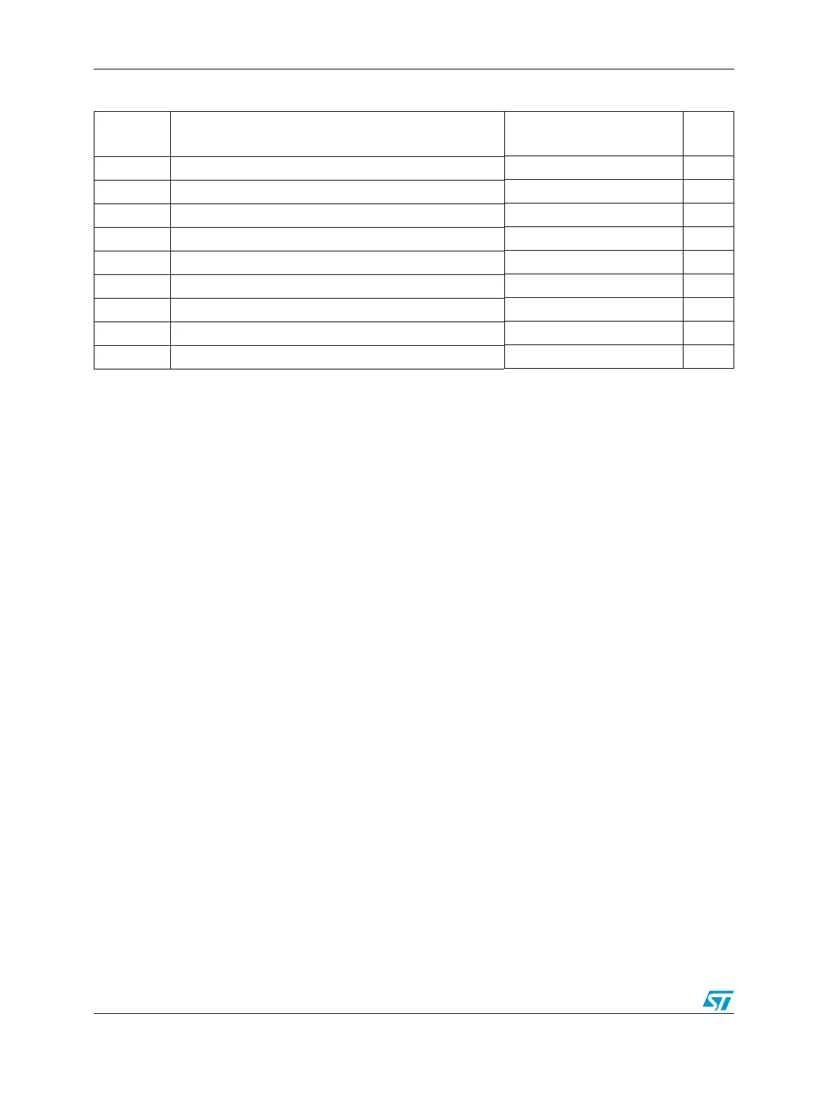
Table 145. Shadow sector structure
Name Description Addresses
Size
(bytes)
— User Area 0x0020_0000–0x0020_3DCF 15824
— Reserved 0x0020_3DD0–0x0020_3DD7 8
NVPWD0–1 Non-volatile private censorship password 0–1 registers 0x0020_3DD8–0x0020_3DDF 8
NVSCI0–1 Non-volatile system censorship information 0–1 registers 0x0020_3DE0–0x0020_3DE7 8
— Reserved 0x0020_3DE8–0x0020_3DFF 24
NVBIU2–3 Non-volatile bus interface unit 2–3 registers 0x0020_3E00–0x0020_3E0F 16
— Reserved 0x0020_3E10–0x0020_3E17 8
NVUSRO Non-volatile user options register 0x0020_3E18–0x0020_3E1F 8
— Reserved 0x0020_3E20–0x0020_3FFF 480