eTimer RM0046
714/936 Doc ID 16912 Rev 5
Control register 1 (CTRL1)
Table 371. CNTR field descriptions
Field Description
CNTR[15:0]
Contains the count value for this channel of the eTimer module.
This register is not byte accessible.
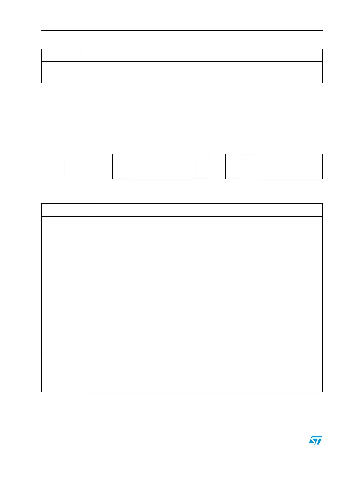
Figure 399. Control register 1 (CTRL1)
Address:
Base + 0x000E(eTimer0)
Base + 0x002E (eTimer1)
Base + 0x004E (eTimer2)
Base + 0x006E (eTimer3)
Base + 0x008E (eTimer4)
Base + 0x00AE (eTimer5)
Access: User read/write
0123456789101112131415
R
CNTMODE[2:0] PRISRC[4:0]
ONCE
LENGTH
DIR SECSRC[4:0]
W
Reset0000000000000000
Table 372. CTRL1 field descriptions
Field Description
CNTMODE[2:0]
Count Mode
These bits control the basic counting and behavior of the counter.
000 No Operation.
001 Count rising edges of primary source. Rising edges counted only when PIPS = 0. Falling
edges counted when PIPS = 1. If primary count source is IP bus clock, only rising edges
are counted regardless of PIPS value.
010 Count rising and falling edges of primary source. IP Bus clock divide by 1 can not be used
as a primary count source in edge count mode.
011 Count rising edges of primary source while secondary input high active.
100 Quadrature count mode, uses primary and secondary sources.
101 Count primary source rising edges, secondary source specifies direction (1 = minus).
Rising edges counted only when PIPS = 0. Falling edges counted when PIPS = 1.
110 Edge of secondary source triggers primary count till compare.
111 Cascaded counter mode, up/down. Primary count source must be set to one of the counter
outputs.
PRISRC
Primary Count Source
These bits select the primary count source. See Tabl e 3 73.
A timer cannot select its own output as its primary count source. If this is done, the timer will not count.
ONCE
Count Once
This bit selects continuous or one-shot counting mode.
0 Count repeatedly.
1 Count until compare and then stop. When output mode 0x4 is used, the counter reinitializes
after reaching the COMP1 value and continues to count to the COMP2 value, then stops.

 Loading...