Analog-to-Digital Converter (ADC) RM0046
576/936 Doc ID 16912 Rev 5
the same frequency of MC_PLL_CLK or is half of MC_PLL_CLK, depending on the
value of the bit ADCLKSEL.
● CTUEN field in the MCR: Enables or disables CTU control mode
● Registers CDR[16..95] not used
● ADC channel 15 is internally connected to the core voltage
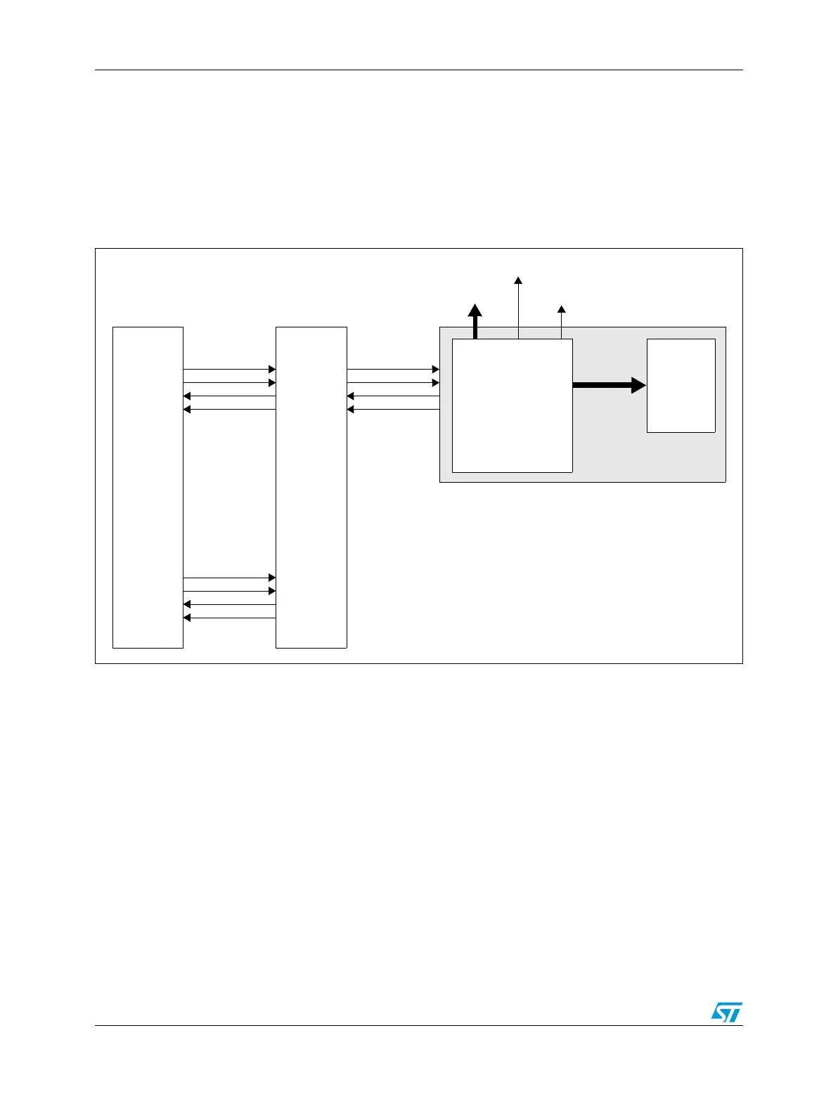
23.1.3 Device-specific implementation
Figure 279. ADC implementation diagram
23.2 Introduction
The analog-to-digital converter (ADC) block provides accurate and fast conversions for a
wide range of applications.
The ADC contains advanced features for normal or injected conversion. It provides support
for eDMA (direct memory access) mode operation. A conversion can be triggered by
software or hardware (Cross Triggering Unit or PIT).
The mask registers present within the ADC can be programmed to configure the channel to
be converted.
Analog watchdogs allow continuous hardware monitoring.
DMA
ADC_EOC
ADC
ADC unit 0
ADC_WD
Analog
TRIGGER_0
NEXT_CMD_0
ADC_CMD_0
ADC_DATA_0
Cross
ADC Digital
Interface
Triggering
Unit
CTU/ADC
IP Interface
TRIGGER_1
NEXT_CMD_1
ADC_CMD_1
ADC_DATA_1