Clock Description RM0046
106/936 Doc ID 16912 Rev 5
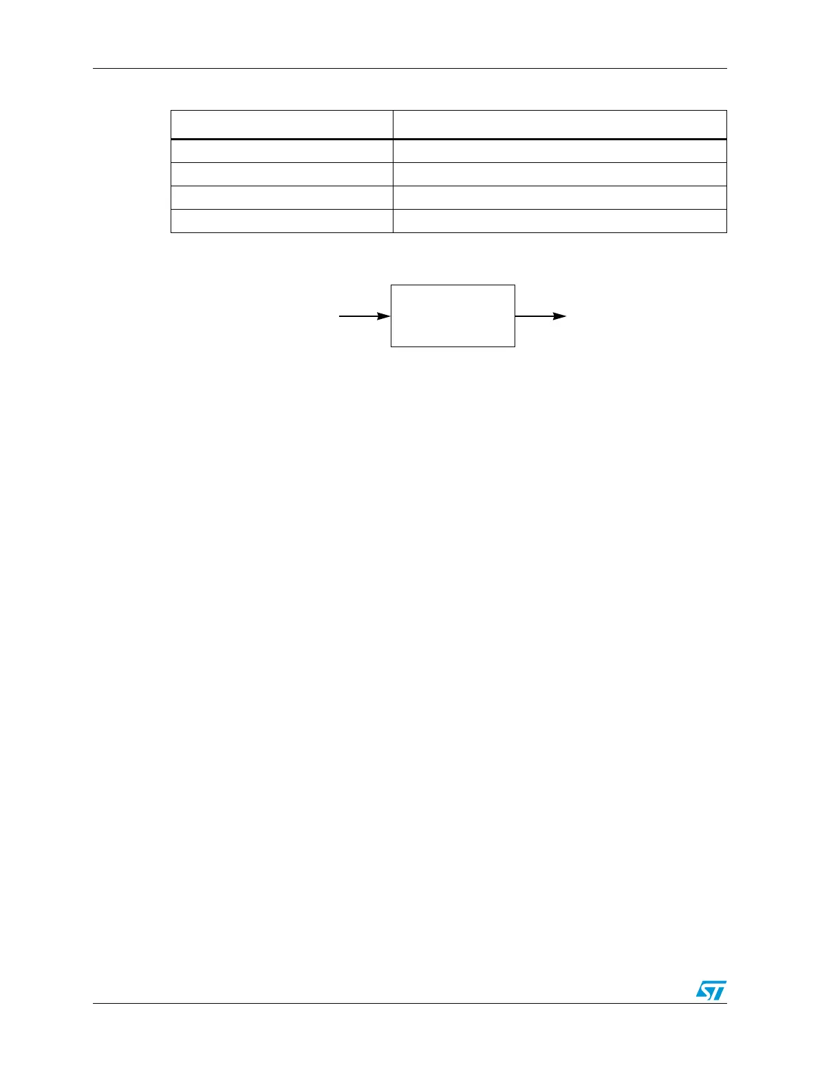
Figure 17. Progressive clock switching scheme
Normal Mode with frequency modulation
The FMPLL default mode is without frequency modulation enabled. When frequency
modulation is enabled, however, two parameters must be set to generate the desired level of
modulation: the PERIOD, and the STEP. The modulation waveform is always a triangle wave
and its shape is not programmable.
Frequency modulation is activated as follows:
1. Configure the FM modulation characteristics: MOD_PERIOD, INC_STEP.
2. Enable the FM modulation by programming bit SSCG_EN of the MR to ‘1’. FM
modulated mode can be enabled only when PLL is in lock state.
There are two ways to latch these values inside the FMPLL, depending on the value of bit
STRB_BYPASS in the MR.
If STRB_BYPASS is low, the modulation parameters are latched in the PLL only when the
strobe signal goes high. The strobe signal is automatically generated in the FMPLL when
the modulation is enabled (SSCG_EN goes high) if the PLL is locked (s_lock = 1) or when
the modulation has been enabled (SSCG_EN = 1) and PLL enters in lock state (s_lock goes
high).
If STRB_BYPASS is high, the strobe signal is bypassed. In this case, control bits
(MOD_PERIOD[12:0], INC_STEP[14:0], SPREAD_CONTROL) must be changed only
when the PLL is in power down mode.
The modulation depth in % is
Equation 2
Note: The user must ensure that the product of INCSTEP and MODPERIOD is less than (2
15
–1).
Table 15. Progressive clock switching on pll_select rising edge
Number of PLL output clock cycles ck_pll_div frequency (PLL output frequency)
8 (ck_pll_out frequency) 8
16 (ck_pll_out frequency) 4
32 (ck_pll_out frequency) 2
onward (ck_pll_out frequency)
Division factors
ck_pll_out ck_pll_div
of 8, 4, 2, or 1
ModulationDepth
100 5 INCSTEPxMODPERIOD
2
15
1–MDF
-------------------------------------------------------------------------------------------------
=