RM0046 Nexus Development Interface (NDI)
Doc ID 16912 Rev 5 879/936
Debug Control Register 4 (DBCR4)
Debug Control Register 4 is used to extend data value compare matching functionality.
DBCR4 is shown in Figure 510.
Table 462 provides bit definitions for Debug Control Register 4.
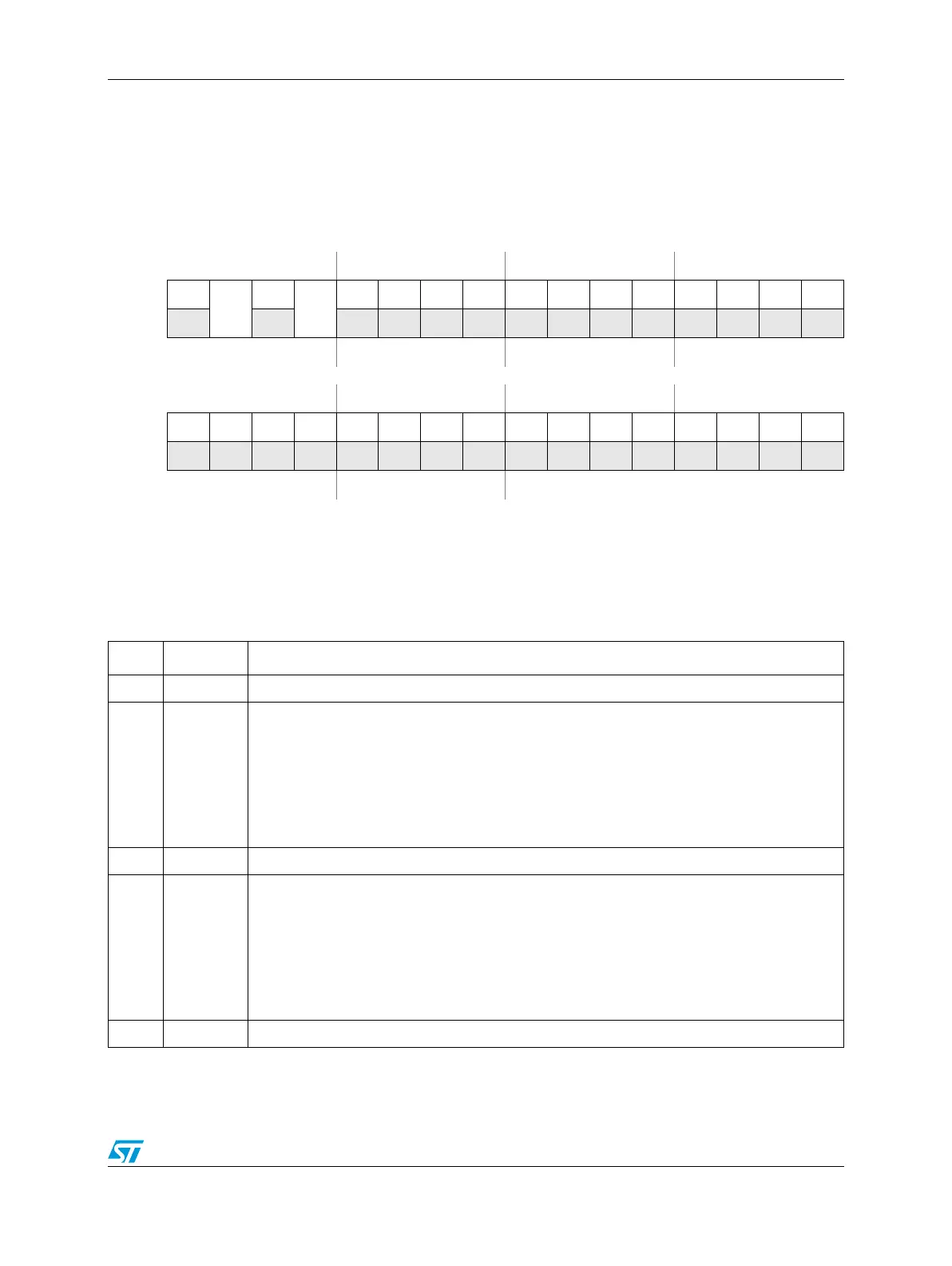
Figure 510. DBCR4 Register
SPR - 563
0123456789101112131415
R0
DVC1C
0
DVC2C
000000000000
W
Reset
(1)
0000000000000000
16 17 18 19 20 21 22 23 24 25 26 27 28 29 30 31
R0000000000000000
W
Reset0000000000000000
1. DBCR4 is reset by processor reset p_reset_b if DBCR0
EDM
=0, as well as unconditionally by m_por. If DBCR0
EDM
=1,
DBERC0 masks off hardware-owned resources from reset by p_reset_b and only software-owned resources indicated by
DBERC0 will be reset by p_reset_b.
Table 462. DBCR4 Bit Definitions
Bit(s) Name Description
17:20 — Reserved
0DVC1C
Data Value Compare 1 Control
0 – Normal DVC1 operation.
1 – Inverted polarity DVC1 operation
DVC1C controls whether DVC1 data value comparisons utilize the normal BookE operation,
or an alternate “inverted compare” operation. In inverted polarity mode, data value compares
perform a not-equal comparison. See details in the DBCR2 register definition
2—Reserved
3DVC2C
Data Value Compare 2 Control
0 – Normal DVC2 operation.
1 – Inverted polarity DVC2 operation
DVC2C controls whether DVC2 data value comparisons utilize the normal BookE operation,
or an alternate “inverted compare” operation. In inverted polarity mode, data value compares
perform a not-equal comparison. See details in the DBCR2 register definition
4:31 — Reserved