RM0046 Cross Triggering Unit (CTU)
Doc ID 16912 Rev 5 607/936
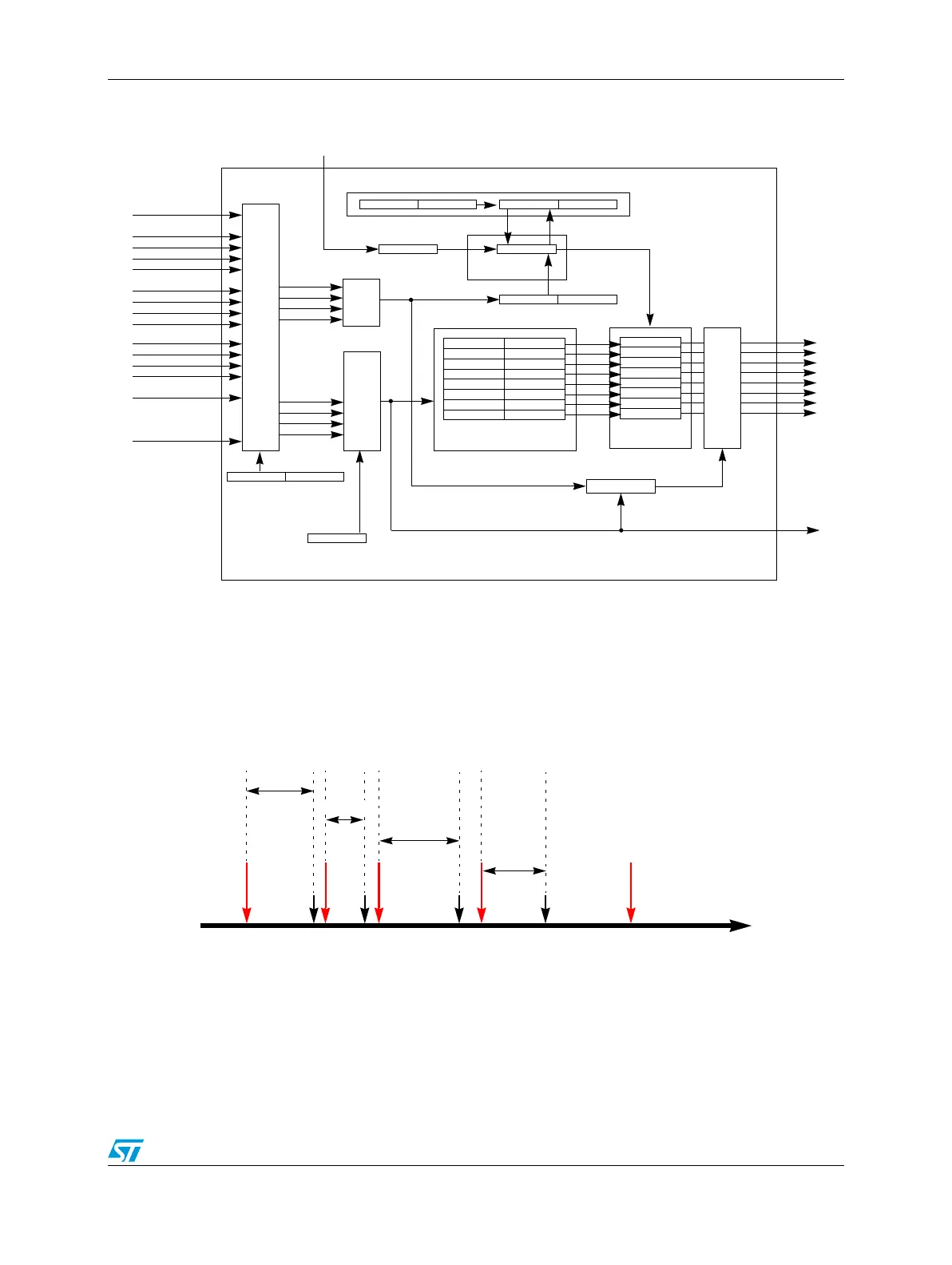
Figure 304. TGS in sequential mode
An example timing diagram for TGS in sequential mode is shown in Figure 305. The red
arrows indicate the MRS occurrences and ES occurrences, while the black arrows indicate
the trigger event occurrences with the relevant delay in respect to the ES occurrence. The
first red arrow indicates the first ES occurrence, which is also the MRS.
Figure 305. Example timing for TGS in sequential mode
24.3.5 TGS counter
The TGS counter is able to count from negative to positive, that is, from 0x8000 to 0x7FFF.
Figure 306 shows examples in order to explain the TGS counter counts. The compare
CTU Clock (as PWM)
EXT_IN
ETIMER0_IN
PWM_REL
PWM_ODD_x
PWM_EVEN_x
RPWM_x
Individual inputs selection
(rising/falling/both edges)
Master Reload
Master Reload Signal (MRS)
Triggers Compare Registers
(double-buffered)
Comparators
TGS Counter Compare Register TGS Counter Comparator
TGS Counter STOP Signal
TGS Counter
TGS Counter Reload Register
Prescaler (1, 2, 3, 4)
Input Selection
32-bit Register
Master Reload Selection
(5 bits in TGS Control Register)
OR
Selection
Mux
Event Signal
3-bit Counter
Clock (ES)
Reset (MRS)
Delay T
0
Delay T
2
Delay T
3
Delay T
1