System Integration Unit Lite (SIUL) RM0046
268/936 Doc ID 16912 Rev 5
possibility of reading back an input or output value of a pad directly. This supports the ability
to validate what is present on the pad rather than merely confirming the value that was
written to the data register by accessing the data input registers.
The data output registers support both read and write operations to be performed.
The data input registers support read access only.
When the pad is configured to use one of its alternate functions, the data input value reflect
the respective value of the pad. If a write operation is performed to the data output register
for a pad configured as an alternate function (non GPIO), this write will not be reflected by
the pad value until reconfigured to GPIO.
The allocation of what input function is connected to the pin is defined by the PSMI registers
(see Section , “Pad Selection for Multiplexed Inputs registers (PSMI[0_3:32_35])).
11.6.4 External interrupts
The SIUL supports 25 external interrupts, EIRQ[0:24]. The signal description chapter of this
reference manual provides a map of the external interrupts.
The SIUL supports four interrupt vectors to the interrupt controller. Each vector interrupt has
eight external interrupts combined together with the presence of flag generating an interrupt
for that vector if enabled. All of the external interrupt pads within a single group have equal
priority.
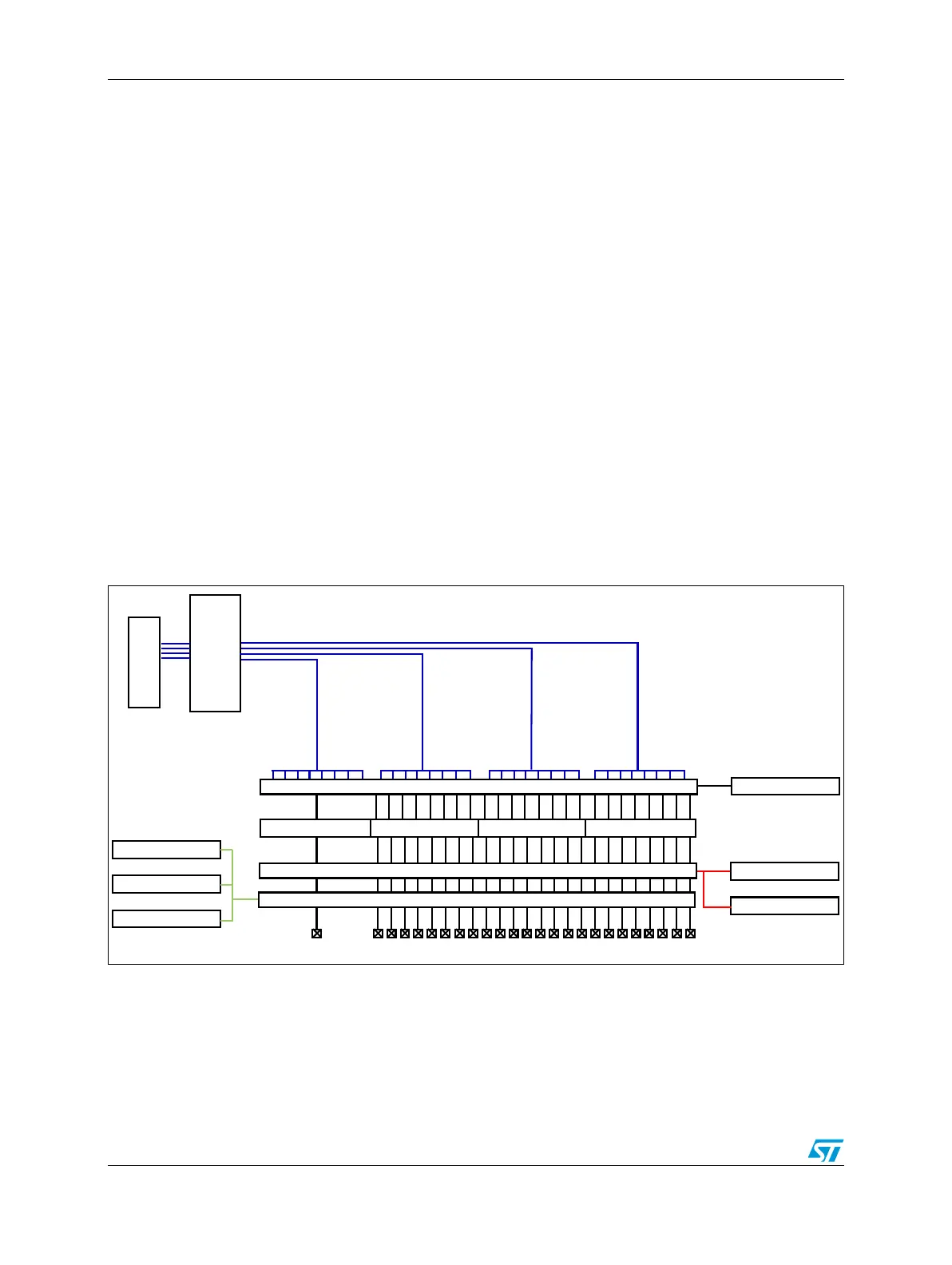
Refer to Figure 115 for an overview of the external interrupt implementation.
Figure 115. External interrupt pad diagram
External interrupt management
Each interrupt can be enabled or disabled independently. This can be performed using the
IRER (see Section , “Interrupt Request Enable Register (IRER)). A pad defined as an
external interrupt can be configured to recognize interrupts with an active rising edge, an
Interrupt
Controller
Interrupt
Vectors
EIF[24] EIF[23:16] EIF[15:8] EIF[7:0]
IRE[24:0]
Pads
IREE[24:0]
Interrupt Edge Enable
IFEE[24:0]
Falling
Rising
Edge Detection
Glitch Filter
IFE[24:0]
MAXCOUNT[x]
IRQ Glitch Filter enable
Glitch filter Counter_n
IFCP[3:0]
Glitch filter Prescaler
Interrupt enable
OR
OR OR OR
IRQ_24
IRQ_23_16
IRQ_15_08
IRQ_07_00