RM0046 Clock Description
Doc ID 16912 Rev 5 109/936
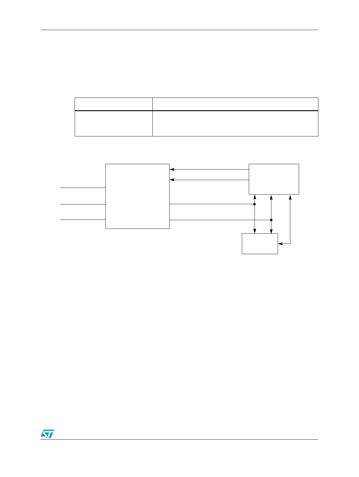
When mismatch occurs in the CMU either with the PLL monitor or the XOSC monitor, the
CMU notifies the RGM, ME and the FCU (Fault Collection Unit) modules. The default
behavior is such that a reset occurs and a status bit is set in the RGM. The user also has
the option to change the behavior of the action by disabling the reset and selecting an
alternate action. The alternate action can be either entering safe mode or generating an
interrupt.
Figure 19. SPC560P40/34CMU
4.9.2 Main features
● RC oscillator frequency measurement
● External oscillator clock monitoring with respect to CK_IRC/n clock
● PLL clock frequency monitoring with respect to CK_IRC/4 clock
● Event generation for various failures detected inside monitoring unit
Table 16. CMU module summary
Module Monitored clocks
CMU_0
– XOSC integrity supervisor
– FMPLL_0 integrity supervisor
– IRCOSC frequency meter
IRC_CLK
XOSC_CLK
FMPLL_0
16 MHz
4 to 40 MHz
64 MHz
CK 0 (reference)
CK XOSC
CK PLL
XOSC valid (on AND stable) / off
CMU_0
FLL
OLR
FMPLL_0 valid (on AND locked) / off
FCU
FMPLL_0 freq.
out of range
Loss of crystal
Clock
Control
Logic