DMA Channel Mux (DMA_MUX) RM0046
430/936 Doc ID 16912 Rev 5
Figure 201. DMA mux triggered channels diagram
The DMA channel triggering capability allows the system to “schedule” regular DMA
transfers, usually on the transmit side of certain peripherals, without the intervention of the
processor. This trigger works by gating the request from the peripheral to the DMA until a
trigger event has been seen. This is illustrated in Figure 202.
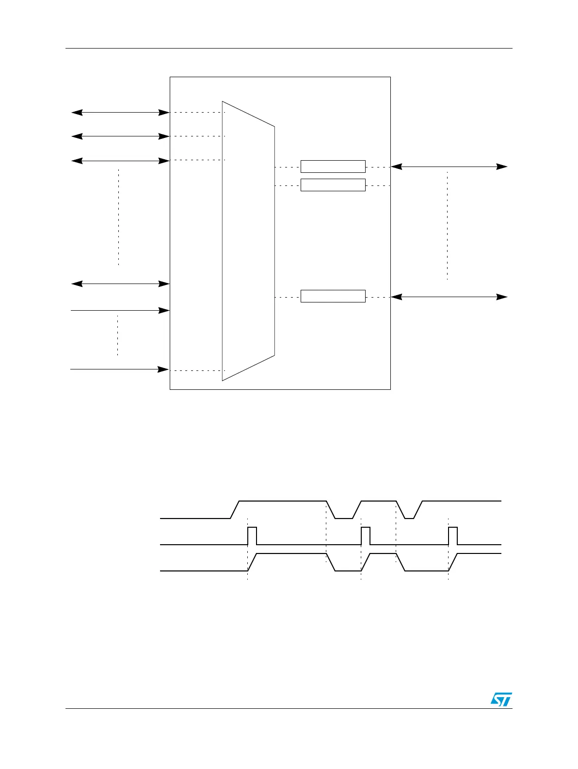
Figure 202. DMA mux channel triggering: normal operation
Once the DMA request has been serviced, the peripheral will negate its request, effectively
resetting the gating mechanism until the peripheral re-asserts its request AND the next
trigger event is seen. This means that if a trigger is seen, but the peripheral is not requesting
a transfer, that triggered will be ignored. This situation is illustrated in Figure 203.
DMA Channel #0
DMA Channel #3
Trigger #4
Trigger #2
Trigger #1
Source #1
Source #2
Source #3
Source #21
Always #1
Always #9
Peripheral Request
Tr i gger
DMA Request