Flash Memory RM0046
362/936 Doc ID 16912 Rev 5
User Test 1 register (UT1)
The User Test 1 register allows to enable the checks on the ECC logic related to the 32 LSB
of the Double Word.
The User Test 1 register is not accessible whenever MCR[DONE] or UT0[AID] are low.
Reads return indeterminate data. Writes have no effect.
AIS
29
Array Integrity Sequence
AIS determines the address sequence to be used during array integrity checks or Margin Mode.
The default sequence (AIS = 0) is meant to replicate sequences normal user code follows, and
thoroughly checks the read propagation paths. This sequence is proprietary.
The alternative sequence (AIS = 1) is just logically sequential.
It should be noted that the time to run a sequential sequence is significantly shorter than the time
to run the proprietary sequence.
This bit is not accessible whenever MCR[DONE] or UT0[AID] are low. Reads return indeterminate
data, and writes have no effect. In Margin Mode only the linear sequence (AIS = 1) is allowed,
while the proprietary sequence (AIS = 0) is forbidden.
0 Array Integrity sequence is a proprietary sequence.
1 Array Integrity or Margin Mode sequence is sequential.
AIE
31
Array Integrity Enable
AIE set to 1 starts the Array Integrity Check done on all selected and unlocked blocks.
The pattern is selected by AIS, and the MISR (UMISR0–4) can be checked after the operation is
complete, to determine if a correct signature is obtained.
AIE can be set only if MCR[ERS], MCR[PGM], and MCR[EHV] are all low.
0 Array Integrity Checks are disabled.
1 Array Integrity Checks are enabled.
AID
31
Array Integrity Done
AID is cleared upon an Array Integrity Check being enabled (to signify the operation is on-going).
Once completed, AID is set to indicate that the Array Integrity Check is complete. At this time, the
MISR (UMISR0–4) can be checked.
0 Array Integrity Check is on-going.
1 Array Integrity Check is done.
Table 159. UT0 field descriptions (continued)
Field Description
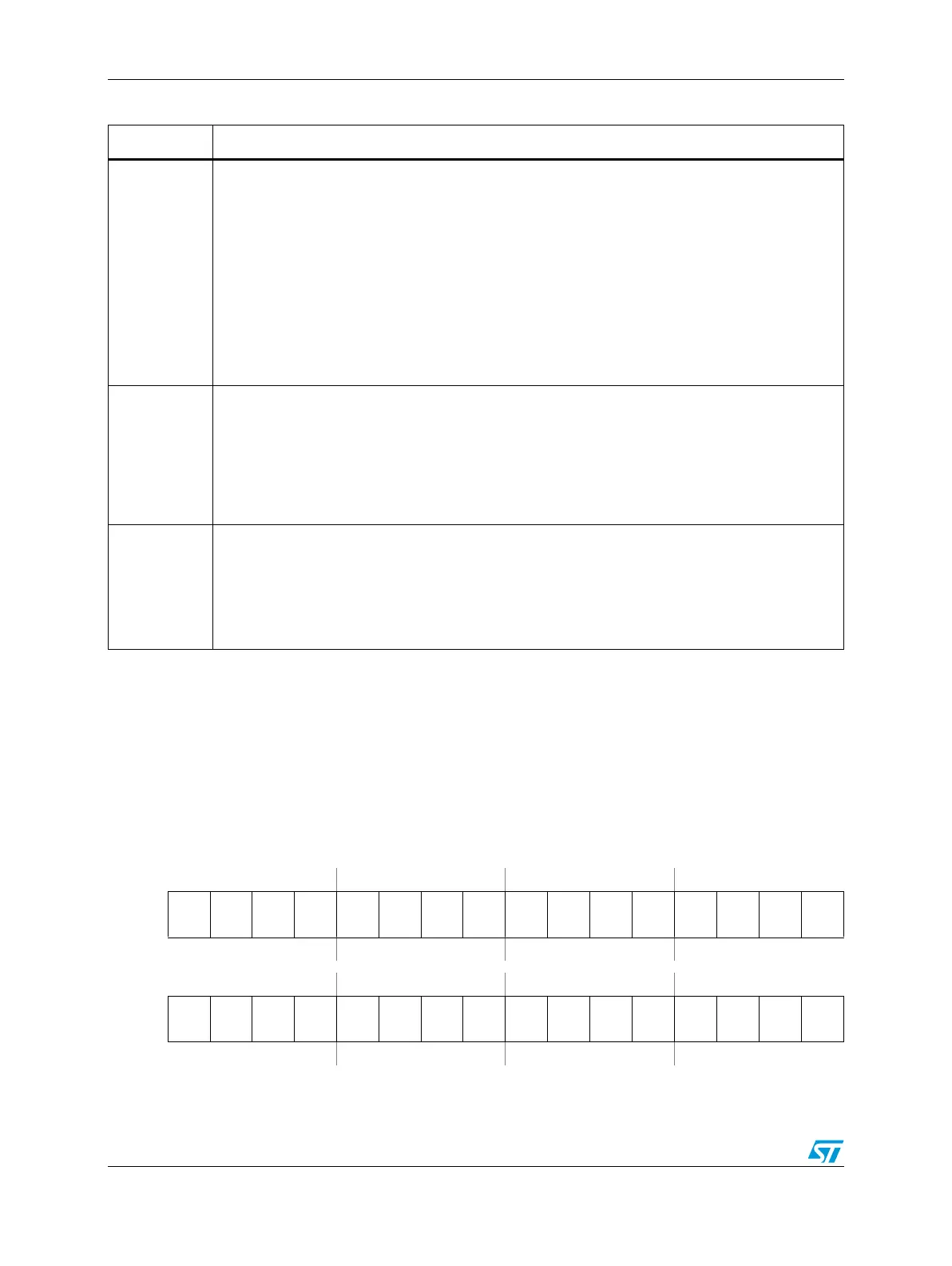
Figure 164. User Test 1 register (UT1)
Address:
Base + 0x0040 Access: User read/write
0123456789101112131415
R
DAI
31
DAI
30
DAI
29
DAI
28
DAI
27
DAI
26
DAI
25
DAI
24
DAI
23
DAI
22
DAI
21
DAI
20
DAI
19
DAI
18
DAI
17
DAI
16
W
Reset0000000000000000
16 17 18 19 20 21 22 23 24 25 26 27 28 29 30 31
R
DAI
15
DAI
14
DAI
13
DAI
12
DAI
11
DAI
10
DAI
9
DAI
8
DAI
7
DAI
6
DAI
5
DAI
4
DAI
3
DAI
2
DAI
1
DAI
0
W
Reset0000000000000000