Cross Triggering Unit (CTU) RM0046
604/936 Doc ID 16912 Rev 5
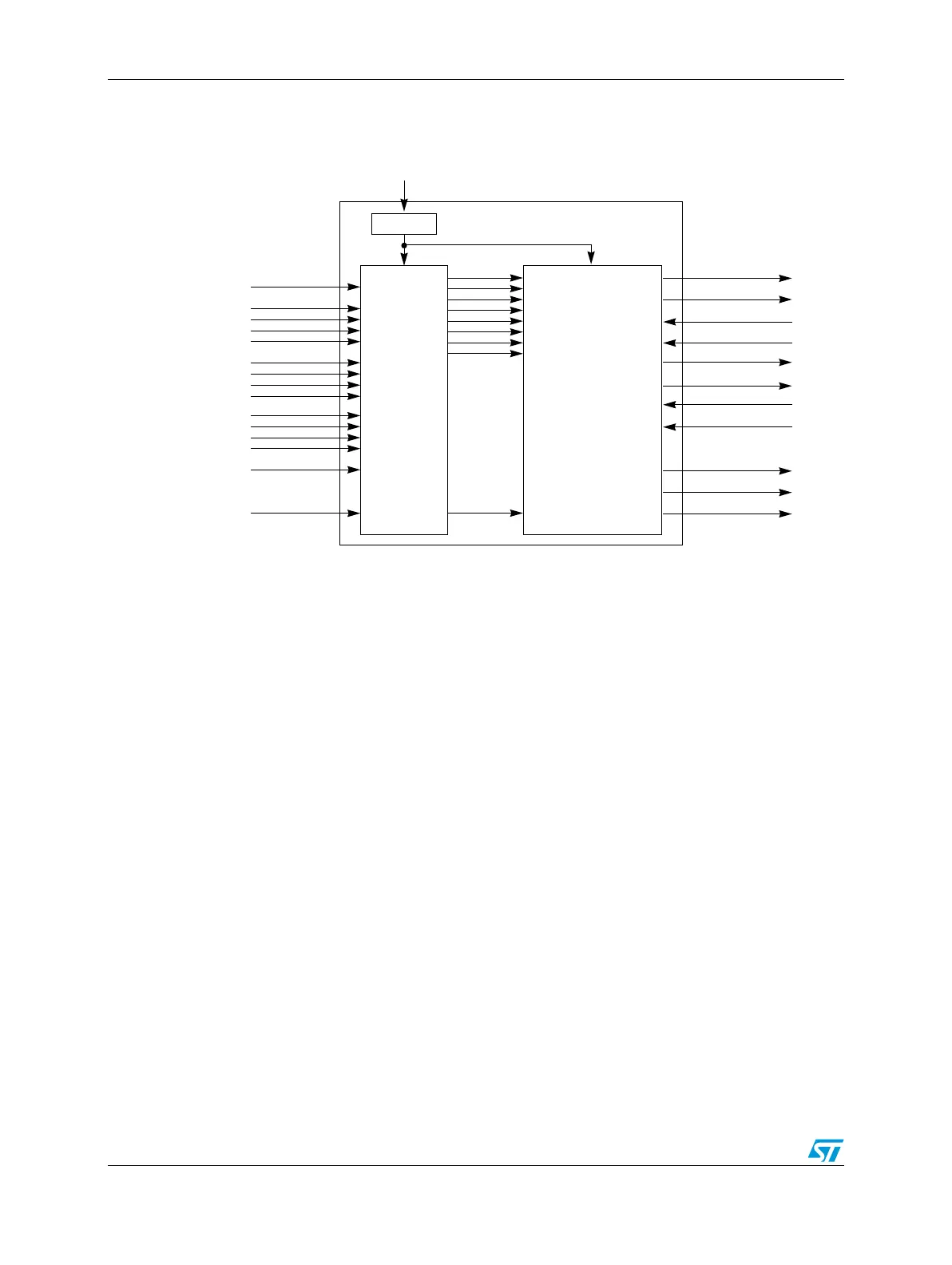
Figure 301. Cross triggering unit diagram
The CTU consists of two subunits:
● Trigger generator
● Scheduler
The trigger generator subunit handles incoming signals, selecting for each signal, the active
edges to generate the Master Reload signal, and generates as many as eight trigger events
(signals). The scheduler subunit generates the trigger event output according to the
occurred trigger event (signal).
24.3 Functional description
The following describes the functionality of the CTU.
24.3.1 Trigger events features
The TGS has the capability to generate as many as eight trigger events. Each trigger event
has the following characteristics:
● Generation of the trigger event is sequential in time
● The triggers list uses eight 16-bit double-buffered registers
● On each Master Reload Signal (MRS), the new triggers list is loaded
● The triggers list is reloaded on a MRS occurrence, only if the reload enable bit is set
CTU Clock (as PWM)
TRIGGER_0
ETIMER0_TRG
ADC_CMD_0
FIFO_0
TRIGGER_1
FIFO_1
NEXT_CMD_0
NEXT_CMD_1
ADC_CMD_1
EXT_TRG
EXT_IN
ETIMER0_IN
PWM_REL
PWM_ODD_x
PWM_EVEN_x
RPWM_x
MRS
Prescaler
Trigger
Generator
Subunit
Scheduler
Subunit
ETIMER1_TRG