RM0046 FlexPWM
Doc ID 16912 Rev 5 693/936
To correct deadtime distortion, software can decrease or increase the value in the
appropriate VALx register.
● In edge-aligned operation, decreasing or increasing the PWM value by a correction
value equal to the deadtime typically compensates for deadtime distortion.
● In center-aligned operation, decreasing or increasing the PWM value by a correction
value equal to one-half the deadtime typically compensates for deadtime distortion.
25.8.10 Manual correction
To detect the current status, the voltage on each PWMx pin is sampled twice in a PWM
period, at the end of each deadtime. The value is stored in the DTx bits in the CTRL1
register. The DTx bits are a timing marker especially indicating when to toggle between
PWM value registers. Software can then set the IPOL bit to switch between VAL2/VAL3 and
VAL4/VAL5 register pairs according to DTx values.
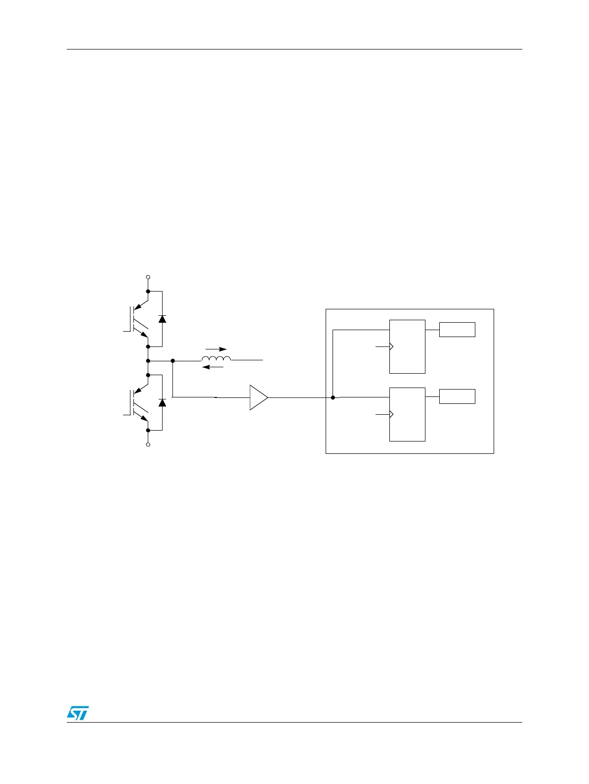
Figure 379. Current-status sense scheme for deadtime correction
Both D flip-flops latch low, DT0 = 0, DT1 = 0, during deadtime periods if current is large and
flowing out of the complementary circuit. See Figure 379. Both D flip-flops latch the high,
DT0 = 1, DT1 = 1, during deadtime periods if current is also large and flowing into the
complementary circuit.
However, under low-current, the output voltage of the complementary circuit during
deadtime is somewhere between the high and low levels. The current cannot free-wheel
through the opposition anti-body diode, regardless of polarity, giving additional distortion
when the current crosses zero. Sampled results will be DT0 = 0 and DT1 = 1. Thus, the best
time to change one PWM value register to another is just before the current zero crossing.
PWMA
PWMB
DQ
CLK
DQ
CLK
Voltage
sensor
PWMX
PWMA
PWMB
DT0
DT1
Positive
current
Negative
current