LIN Controller (LINFlex) RM0046
518/936 Doc ID 16912 Rev 5
21.8 Functional description
21.8.1 UART mode
The main features in the UART mode are
● Full duplex communication
● 8- or 9-bit data with parity
● 4-byte buffer for reception, 4-byte buffer for transmission
● 8-bit counter for timeout management
8-bit data frames: The 8th bit can be a data or a parity bit. Even/Odd Parity can be selected
by the Odd Parity bit in the UARTCR. An even parity is set if the modulo-2 sum of the 7 data
bits is 1. An odd parity is cleared in this case.
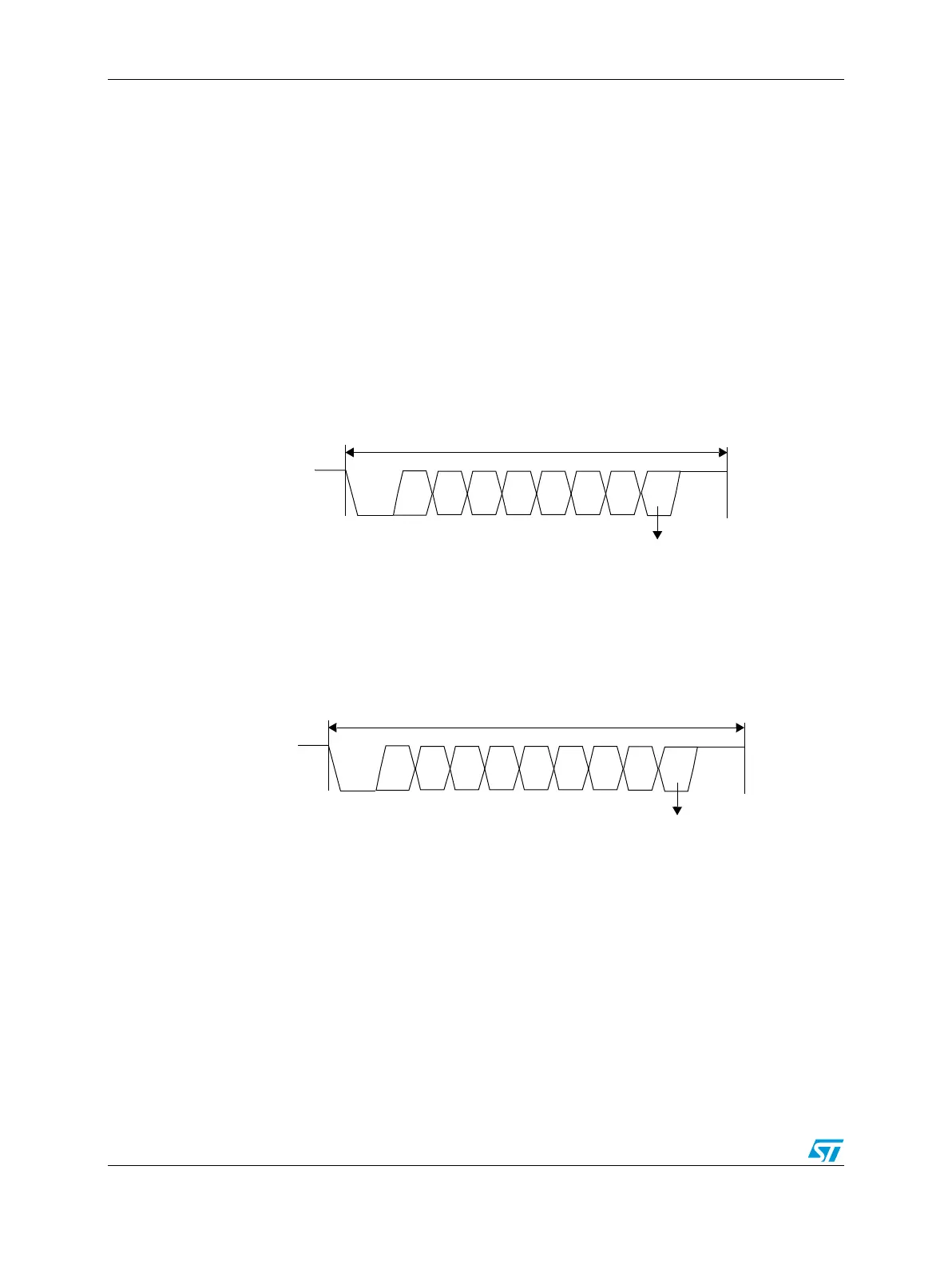
Figure 256. UART mode 8-bit data frame
9-bit frames: The 9th bit is a parity bit. Even/Odd Parity can be selected by the Odd Parity
bit in the UARTCR. An even parity is set if the modulo-2 sum of the 8 data bits is 1. An odd
parity is cleared in this case.
Figure 257. UART mode 9-bit data frame
Buffer in UART mode
The 8-byte buffer is divided into two parts: one for receiver and one for transmitter as shown
in Table 260.
Start
bit
D0
D7
Stop
bit
Byte Field
— Data bit
— Parity bit
D1 D2 D3 D4 D5 D6
Start
bit
D0
D7
Stop
bit
Byte Field
— Parity bit
D1 D2 D3 D4 D5 D6
D8