Periodic Interrupt Timer (PIT) RM0046
786/936 Doc ID 16912 Rev 5
Timer Control Register n (TCTRLn)
The TCTRL register contains the control bits for each timer.
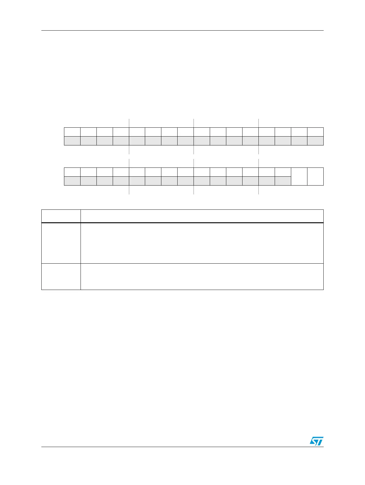
Figure 460. Timer Control register n (TCTRLn)
Address:
Channel Base + 0x0008
TCTRL0 = PIT_BASE + 0x0108
TCTRL1 = PIT_BASE + 0x0118
TCTRL2 = PIT_BASE + 0x0128
TCTRL3 = PIT_BASE + 0x0138
Access: User read/write
0123456789101112131415
R00000000 00000 000
W
Reset0000000000000000
16 17 18 19 20 21 22 23 24 25 26 27 28 29 30 31
R00000000 000000
TIE TEN
W
Reset0000000000000000
Table 421. TCTRLn field descriptions
Field Description
TIE
Timer Interrupt Enable Bit
0: Interrupt requests from Timer x are disabled
1: Interrupt will be requested whenever TIF is set
When an interrupt is pending (TIF set), enabling the interrupt will immediately cause an interrupt
event. To avoid this, the associated TIF flag must be cleared first.
TEN
Timer Enable Bit
0: Timer will be disabled
1: Timer will be active