Deserial Serial Peripheral Interface (DSPI) RM0046
448/936 Doc ID 16912 Rev 5
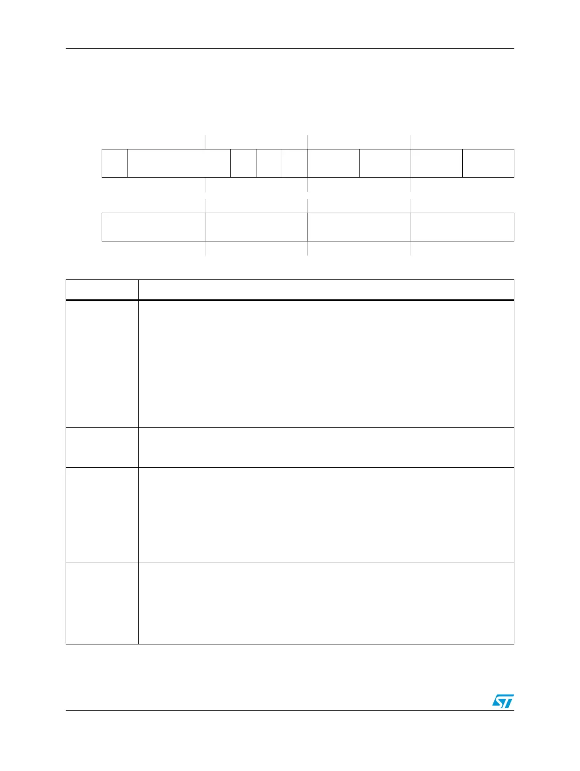
Figure 209. DSPI Clock and Transfer Attributes Registers 0–7 (DSPIx_CTARn)
Address:
Base + 0x000C (DSPIx_CTAR0)
Base + 0x0010 (DSPIx_CTAR1)
Base + 0x0014 (DSPIx_CTAR2)
Base + 0x0018 (DSPIx_CTAR3)
Base + 0x001C (DSPIx_CTAR4)
Base + 0x0020 (DSPIx_CTAR5)
Base + 0x0024 (DSPIx_CTAR6)
Base + 0x0028 (DSPIx_CTAR7)
Access: User read/write
0123456789101112131415
R
DBR FMSZ
CPOL
CPHA
LSB
FE
PCSSCK PASC PDT PBR
W
Reset0111100000000000
16 17 18 19 20 21 22 23 24 25 26 27 28 29 30 31
R
CSSCK ASC DT BR
W
Reset0000000000000000
Table 208. DSPIx_CTARn field descriptions
Field Descriptions
0
DBR
Double Baud Rate
The DBR bit doubles the effective baud rate of the Serial Communications Clock (SCK). This
field is only used in Master Mode. It effectively halves the Baud Rate division ratio supporting
faster frequencies and odd division ratios for the Serial Communications Clock (SCK). When the
DBR bit is set, the duty cycle of the Serial Communications Clock (SCK) depends on the value in
the Baud Rate Prescaler and the Clock Phase bit as listed in Table 209. See the BR[0:3] field
description for details on how to compute the baud rate. If the overall baud rate is divide by two
or divide by three of the system clock then neither the Continuous SCK Enable or the Modified
Timing Format Enable bits should be set.
0 The baud rate is computed normally with a 50/50 duty cycle.
1 The baud rate is doubled with the duty cycle depending on the baud rate prescaler.
1–4
FMSZ[0:3]
Frame Size
The FMSZ field selects the number of bits transferred per frame. The FMSZ field is used in
Master Mode and Slave Mode. Table 210 lists the frame size encodings.
5
CPOL
Clock Polarity
The CPOL bit selects the inactive state of the Serial Communications Clock (SCK). This bit is
used in both Master and Slave Mode. For successful communication between serial devices, the
devices must have identical clock polarities. When the Continuous Selection Format is selected,
switching between clock polarities without stopping the DSPI can cause errors in the transfer
due to the peripheral device interpreting the switch of clock polarity as a valid clock edge.
0 The inactive state value of SCK is low.
1 The inactive state value of SCK is high.
6
CPHA
Clock Phase
The CPHA bit selects which edge of SCK causes data to change and which edge causes data to
be captured. This bit is used in both Master and Slave Mode. For successful communication
between serial devices, the devices must have identical clock phase settings. Continuous SCK
is only supported for CPHA = 1.
0 Data is captured on the leading edge of SCK and changed on the following edge.
1 Data is changed on the leading edge of SCK and captured on the following edge.