RM0046 FlexPWM
Doc ID 16912 Rev 5 691/936
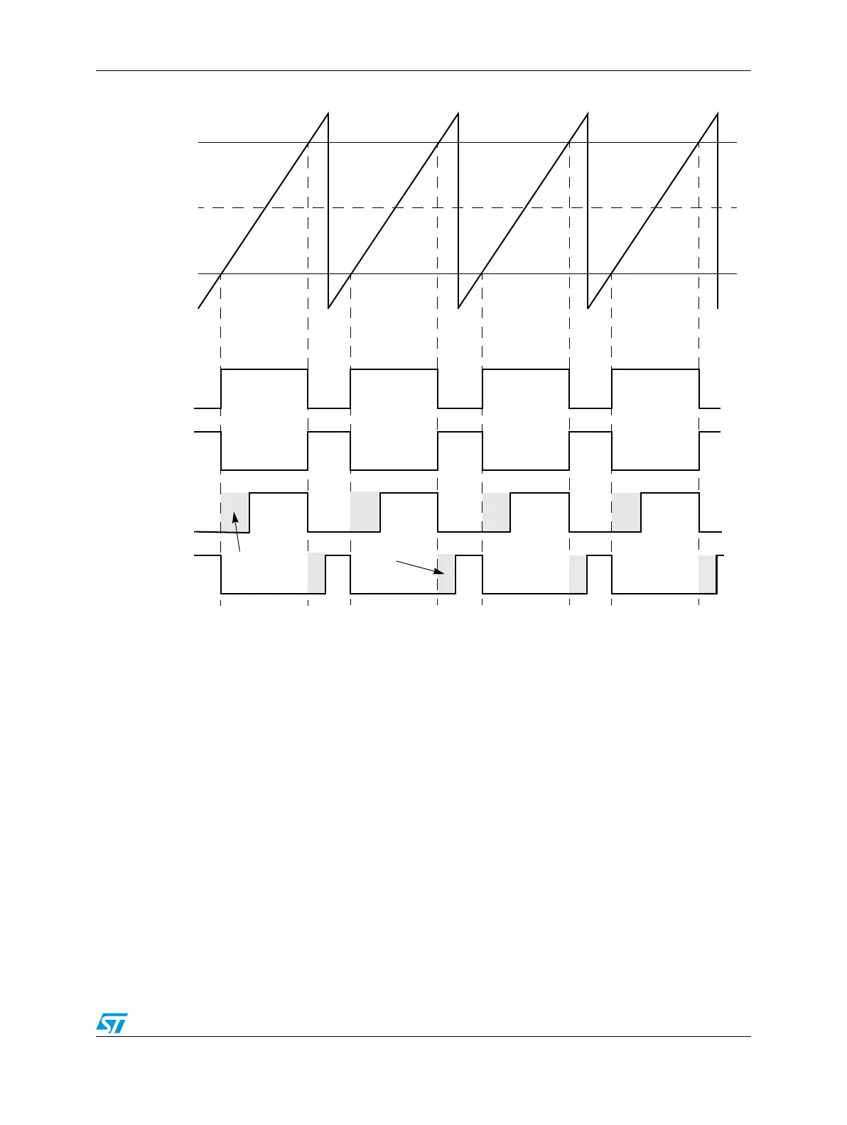
Figure 377. Deadtime insertion
25.8.9 Top/bottom correction
In complementary mode, either the top or the bottom transistor controls the output voltage.
However, deadtime has to be inserted to avoid overlap of conducting interval between the
top and bottom transistor. Both transistors in complementary mode are off during deadtime,
allowing the output voltage to be determined by the current status of load and introduce
distortion in the output voltage. See Figure 378. On AC induction motors running open-loop,
the distortion typically manifests itself as poor low-speed performance, such as torque ripple
and rough operation.
VAL1 (0x0100)
VAL3
VAL0 (0x0000)
VAL2
INIT (0xFF00)
PWMA
PWMB
no deadtime
PWMA
PWMB
with deadtime
DTCNT0
DTCNT1