Mid-Band Operation
To operate in the mid-band region, the CIC field or the CTC field in the ADCDCCTLn register must
be programmed to 0x1. This setting causes interrupts or triggers to be generated in the mid-band
region according the operation mode. Only the Always and Once operational modes are available
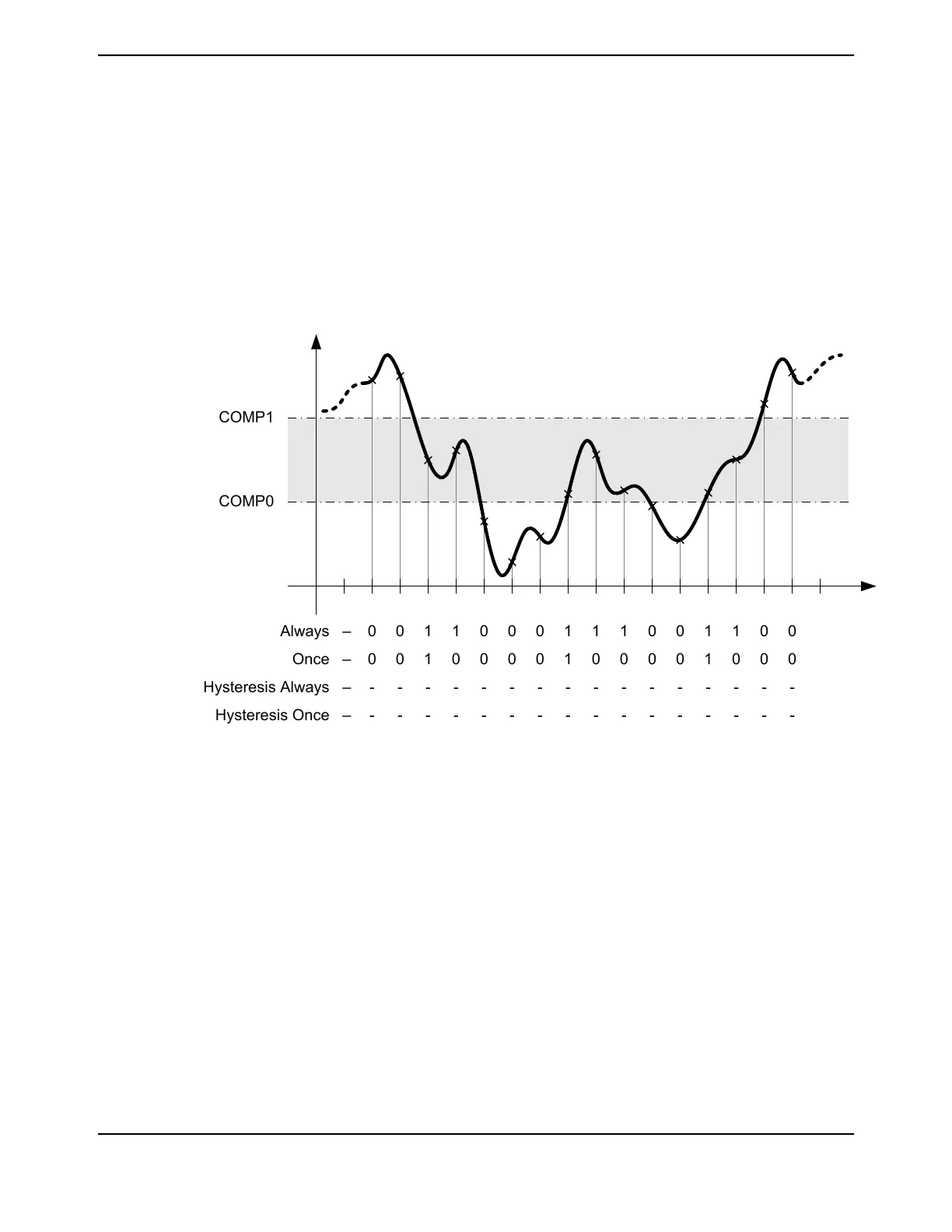
in the mid-band region. An example of the state of the interrupt/trigger signal in the mid-band region
for each of the allowed operational modes is shown in Figure 15-13 on page 1071. Note that a "0" in
a column following the operational mode name (Always or Once) indicates that the interrupt or
trigger signal is deasserted and a "1" indicates that the signal is asserted.
Figure 15-13. Mid-Band Operation (CIC=0x1 and/or CTC=0x1)
0
0
-
-
0
0
-
-
1
1
-
-
1
0
-
-
0
0
-
-
0
0
-
-
0
0
-
-
1
1
-
-
1
0
-
-
1
0
-
-
0
0
-
-
0
0
-
-
1
1
-
-
1
0
-
-
0
0
-
-
0
0
-
-
Always –
Once –
Hysteresis Always –
Hysteresis Once –
COMP0
COMP1
High-Band Operation
To operate in the high-band region, the CIC field or the CTC field in the ADCDCCTLn register must
be programmed to 0x3. This setting causes interrupts or triggers to be generated in the high-band
region according the operation mode. An example of the state of the interrupt/trigger signal in the
high-band region for each of the allowed operational modes is shown in Figure 15-14 on page 1072.
Note that a "0" in a column following the operational mode name (Always, Once, Hysteresis Always,
and Hysteresis Once) indicates that the interrupt or trigger signal is deasserted and a "1" indicates
that the signal is asserted.
1071June 18, 2014
Texas Instruments-Production Data
Tiva
™
TM4C1294NCPDT Microcontroller
 Loading...


