See “External Peripheral Interface (EPI)” on page 1853 for timing details for the SDRAM mode.
11.4.2.1 External Signal Connections
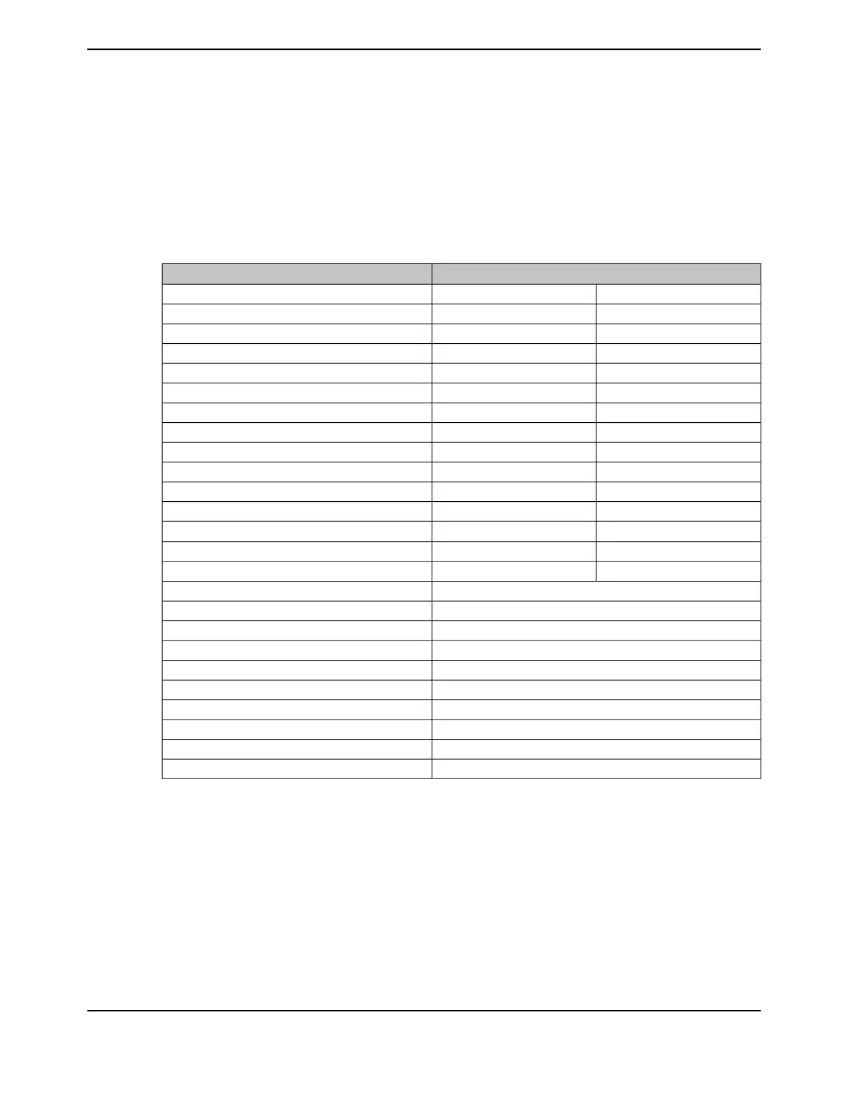
Table 11-3 on page 823 defines how EPI module signals should be connected to SDRAMs. The
table applies when using a x16 SDRAM up to 512 megabits. Note that the EPI signals must use
8-mA drive when interfacing to SDRAM, see page 774. Any unused EPI controller signals can be
used as GPIOs or another alternate function.
Table 11-3. EPI SDRAM x16 Signal Connections
SDRAM Signal
a
EPI Signal
D0A0EPI0S0
D1A1EPI0S1
D2A2EPI0S2
D3A3EPI0S3
D4A4EPI0S4
D5A5EPI0S5
D6A6EPI0S6
D7A7EPI0S7
D8A8EPI0S8
D9A9EPI0S9
D10A10EPI0S10
D11A11EPI0S11
D12A12
b
EPI0S12
D13BA0EPI0S13
D14BA1EPI0S14
D15EPI0S15
DQMLEPI0S16
DQMHEPI0S17
CASnEPI0S18
RASnEPI0S19
not usedEPI0S20-EPI0S27
WEnEPI0S28
CSnEPI0S29
CKEEPI0S30
CLKEPI0S31
a. If two signals are listed, connect the EPI signal to both pins.
b. Only for 256/512 megabit SDRAMs.
11.4.2.2 Refresh Configuration
The refresh count is based on the external clock speed and the number of rows per bank as well
as the refresh period. The RFSH field represents how many external clock cycles remain before an
AUTO-REFRESH is required. The normal formula is:
RFSH = (t
Refresh_us
/ number_rows) / ext_clock_period
A refresh period is normally 64 ms, or 64000 μs. The number of rows is normally 4096 or 8192. The
ext_clock_period is a value expressed in μsec and is derived by dividing 1000 by the clock speed
823June 18, 2014
Texas Instruments-Production Data
Tiva
™
TM4C1294NCPDT Microcontroller
 Loading...


