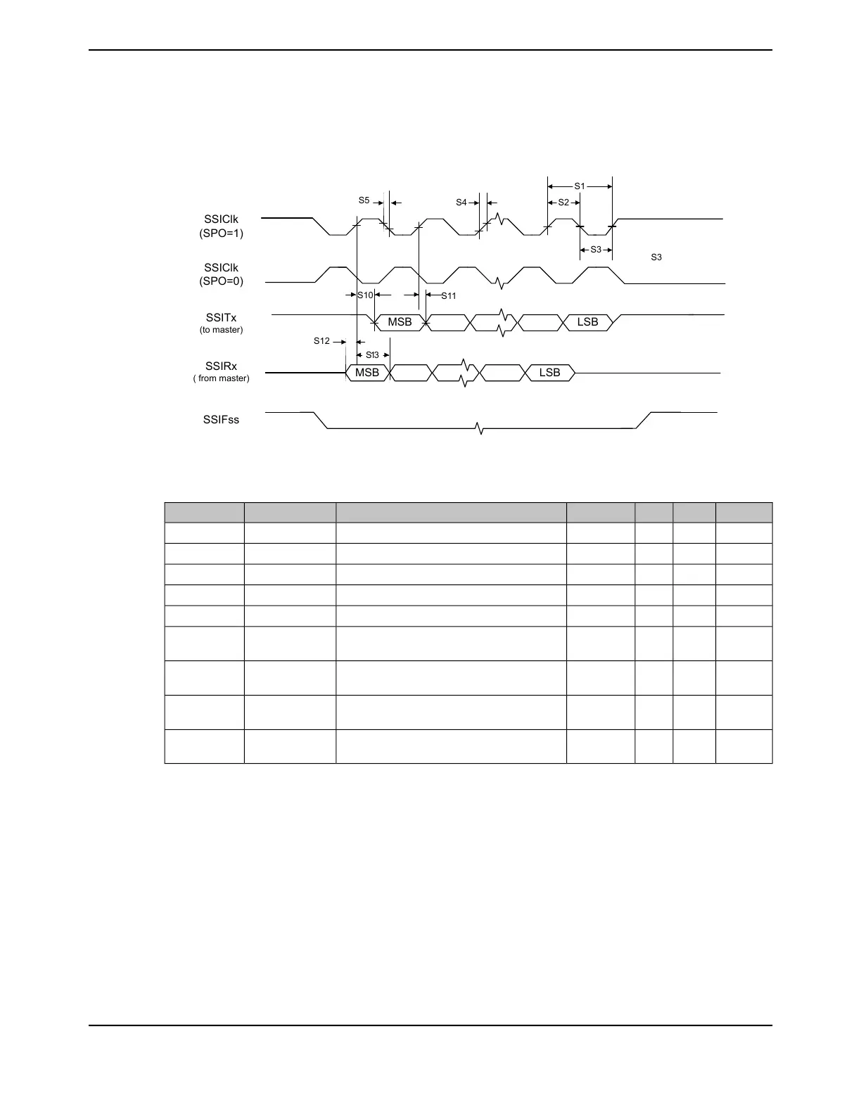
Figure 27-32. Slave Mode SSI Timing for SPI Frame Format (FRF=00), with SPH=1
SSIClk
(SPO=0)
SSITx
(to master)
SSIRx
( from master)
SSIClk
(SPO=1)
S2
S1
S5
SSIFss
LSB
S3
S12
S10
S11
S13
MSB
S4
LSBMSB
S3
Table 27-47. Bi- and Quad-SSI Characteristics
a
UnitMaxNomMinParameter NameParameterParameter No.
ns--16.67SSIClk cycle time, as master
b
T
CLK_PER
S15
ns--8.33SSIClk high time, as masterT
CLK_HIGH
S16
ns--8.33SSIClk low time, as masterT
CLK_LOW
S17
ns--1.25SSIClk rise time
c
T
CLKR
S18
ns--1.25SSIClk fall time
c
T
CLKF
S19
ns4.04--Master Mode: Master SSInXDATn Data Output
(to slave) Valid Time from edge of SSIClk
T
TXDMOV
S20
ns--0.60Master Mode: Master SSInXDATn Data Output
(to slave) Hold Time after next SSIClk
T
TXDMOH
S21
ns--5.78Master Mode: Master SSInXDATn Data In
(from slave) setup time
T
RXDMS
S22
ns--0Master Mode: Master SSInXDATn Data In
(from slave) hold time
T
RXDMH
S23
a. Parameters S15 through S23 correspond to parameters S1 through S9 in Figure 27-30 and Figure 27-31.
b. In master mode, the system clock must be at least twice as fast as the SSIClk.
c. Note that the delays shown are using 12-mA drive strength.
1869June 18, 2014
Texas Instruments-Production Data
Tiva
™
TM4C1294NCPDT Microcontroller
 Loading...


