Table 13-2. General-Purpose Timers Signals (128TQFP) (continued)
DescriptionBuffer TypePin TypePin Mux / Pin
Assignment
Pin NumberPin Name
16/32-Bit Timer 4 Capture/Compare/PWM 0.TTLI/OPM4 (3)
PB0 (3)
PD6 (3)
74
95
127
T4CCP0
16/32-Bit Timer 4 Capture/Compare/PWM 1.TTLI/OPM5 (3)
PB1 (3)
PD7 (3)
73
96
128
T4CCP1
16/32-Bit Timer 5 Capture/Compare/PWM 0.TTLI/OPM6 (3)
PB2 (3)
72
91
T5CCP0
16/32-Bit Timer 5 Capture/Compare/PWM 1.TTLI/OPM7 (3)
PB3 (3)
71
92
T5CCP1
13.3 Functional Description
The main components of each GPTM block are two free-running up/down counters (referred to as
Timer A and Timer B), two prescaler registers, two match registers, two prescaler match registers,
two shadow registers, and two load/initialization registers and their associated control functions.
The exact functionality of each GPTM is controlled by software and configured through the register
interface. Timer A and Timer B can be used individually, in which case they have a 16-bit counting
range for the 16/32-bit GPTM blocks. In addition, Timer A and Timer B can be concatenated to
provide a 32-bit counting range for the 16/32-bit GPTM blocks. Note that the prescaler can only be
used when the timers are used individually.
The available modes for each GPTM block are shown in Table 13-3 on page 958. Note that when
counting down in one-shot or periodic modes, the prescaler acts as a true prescaler and contains
the least-significant bits of the count. When counting up in one-shot or periodic modes, the prescaler
acts as a timer extension and holds the most-significant bits of the count. In input edge count, input
edge time and PWM mode, the prescaler always acts as a timer extension, regardless of the count
direction.
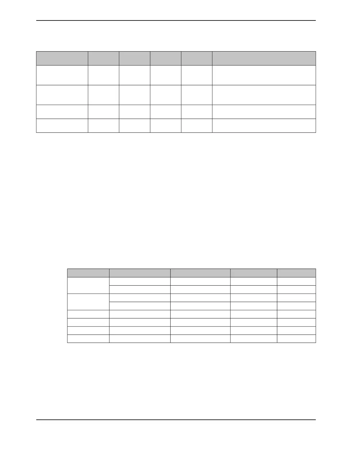
Table 13-3. General-Purpose Timer Capabilities
Prescaler Size
a
Counter SizeCount DirectionTimer UseMode
8-bit16-bitUp or DownIndividual
One-shot
-32-bitUp or DownConcatenated
8-bit16-bitUp or DownIndividual
Periodic
-32-bitUp or DownConcatenated
-32-bitUpConcatenatedRTC
8-bit16-bitUp or DownIndividualEdge Count
8-bit16-bitUp or DownIndividualEdge Time
8-bit16-bitDownIndividualPWM
a. The prescaler is only available when the timers are used individually
Software configures the GPTM using the GPTM Configuration (GPTMCFG) register (see page 976),
the GPTM Timer A Mode (GPTMTAMR) register (see page 977), and the GPTM Timer B Mode
(GPTMTBMR) register (see page 982). When in one of the concatenated modes, Timer A and Timer
B can only operate in one mode. However, when configured in an individual mode, Timer A and
Timer B can be independently configured in any combination of the individual modes.
June 18, 2014958
Texas Instruments-Production Data
General-Purpose Timers
 Loading...


