Register 12: Interrupt 0-31 Set Pending (PEND0), offset 0x200
Register 13: Interrupt 32-63 Set Pending (PEND1), offset 0x204
Register 14: Interrupt 64-95 Set Pending (PEND2), offset 0x208
Register 15: Interrupt 96-113 Set Pending (PEND3), offset 0x20C
Note: This register can only be accessed from privileged mode.
The PENDn registers force interrupts into the pending state and show which interrupts are pending.
Bit 0 of PEND0 corresponds to Interrupt 0; bit 31 corresponds to Interrupt 31. Bit 0 of PEND1
corresponds to Interrupt 32; bit 31 corresponds to Interrupt 63. Bit 0 of PEND2 corresponds to
Interrupt 64; bit 31 corresponds to Interrupt 95. Bit 0 of PEND3 corresponds to Interrupt 96; bit 17
corresponds to interrupt 113.
See Table 2-9 on page 116 for interrupt assignments.
Interrupt 0-31 Set Pending (PEND0)
Base 0xE000.E000
Offset 0x200
Type RW, reset 0x0000.0000
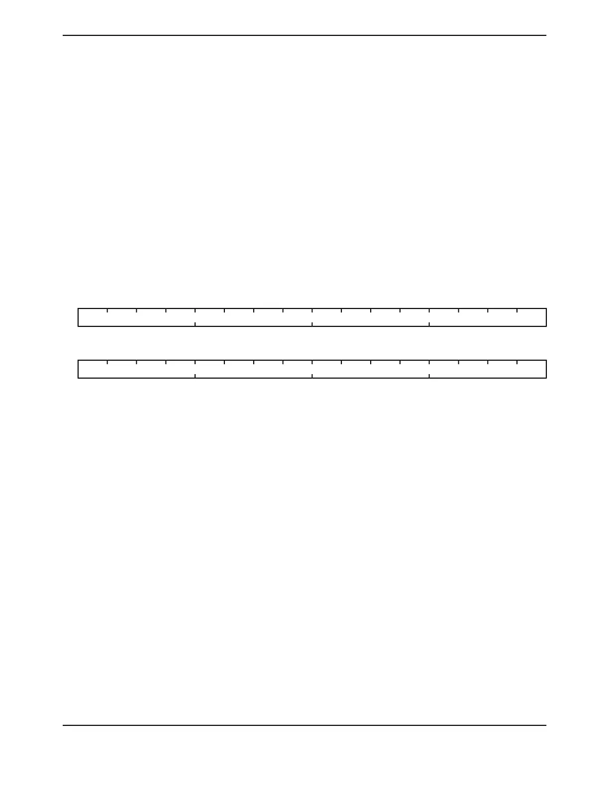
16171819202122232425262728293031
INT
RWRWRWRWRWRWRWRWRWRWRWRWRWRWRWRWType
0000000000000000Reset
0123456789101112131415
INT
RWRWRWRWRWRWRWRWRWRWRWRWRWRWRWRWType
0000000000000000Reset
DescriptionResetTypeNameBit/Field
Interrupt Set Pending
DescriptionValue
On a read, indicates that the interrupt is not pending.
On a write, no effect.
0
On a read, indicates that the interrupt is pending.
On a write, the corresponding interrupt is set to pending
even if it is disabled.
1
If the corresponding interrupt is already pending, setting a bit has no
effect.
A bit can only be cleared by setting the corresponding INT[n] bit in
the UNPEND0 register.
0x0000.0000RWINT31:0
June 18, 2014156
Texas Instruments-Production Data
Cortex-M4 Peripherals
 Loading...


