The TCACT field can be changed while the GPTM is enabled to generate different combinations of
actions. For example, during a periodic event, encodings TCACT = 0x6 or 0x7 can be used to force
the initial state of the CCPn pin before the first interrupt and following that, TCACT=0x2 and TCACT=0x3
can be used (alternately) to change the sense of the pin for the subsequent toggle, while possible
changing load value for the next period.
The time-out interrupts used for one-shot and periodic modes are used in the compare action modes.
Thus, the TnTORIS bits in the GPTMRIS register are triggered if the appropriate mask bits are set
in the GPTMIM register.
13.3.3.2 Real-Time Clock Timer Mode
In Real-Time Clock (RTC) mode, the concatenated versions of the Timer A and Timer B registers
are configured as an up-counter. When RTC mode is selected for the first time after reset, the
counter is loaded with a value of 0x1. All subsequent load values must be written to the GPTM
Timer n Interval Load (GPTMTnILR) registers (see page 1004). If the GPTMTnILR register is loaded
with a new value, the counter begins counting at that value and rolls over at the fixed value of
0xFFFFFFFF. Table 13-6 on page 962 shows the values that are loaded into the timer registers when
the timer is enabled.
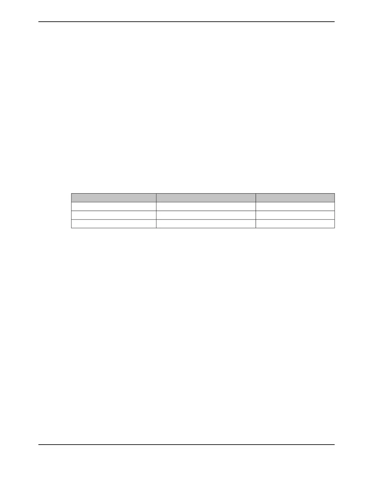
Table 13-6. Counter Values When the Timer is Enabled in RTC Mode
Count Up ModeCount Down ModeRegister
0x1Not availableGPTMTnR
0x1Not availableGPTMTnV
Not availableNot availableGPTMTnPS
The input clock on a CCP0 input is required to be 32.768 KHz in RTC mode. The clock signal is
then divided down to a 1-Hz rate and is passed along to the input of the counter.
When software writes the TAEN bit in the GPTMCTL register, the counter starts counting up from
its preloaded value of 0x1. When the current count value matches the preloaded value in the
GPTMTnMATCHR registers, the GPTM asserts the RTCRIS bit in GPTMRIS and continues counting
until either a hardware reset, or it is disabled by software (clearing the TAEN bit). When the timer
value reaches the terminal count, the timer rolls over and continues counting up from 0x0. If the
RTC interrupt is enabled in GPTMIMR, the GPTM also sets the RTCMIS bit in GPTMMIS and
generates a controller interrupt. The status flags are cleared by writing the RTCCINT bit in GPTMICR.
In this mode, the GPTMTnR and GPTMTnV registers always have the same value.
In addition to generating interrupts, the RTC can generate a μDMA trigger. The μDMA trigger is
enabled by configuring and enabling the appropriate μDMA channel as well as the type of trigger
enable in the GPTM DMA Event (GPTMDMAEV) register. See “Channel Configuration” on page 683.
13.3.3.3 Input Edge-Count Mode
Note: For rising-edge detection, the input signal must be High for at least two clock periods
following the rising edge. Similarly, for falling-edge detection, the input signal must be Low
for at least two clock periods following the falling edge. Based on this criteria, the maximum
input frequency for edge detection is 1/4 of the frequency.
In Edge-Count mode, the timer is configured as a 24-bit up- or down-counter including the optional
prescaler with the upper count value stored in the GPTM Timer n Prescale (GPTMTnPR) register
and the lower bits in the GPTMTnR register. In this mode, the timer is capable of capturing three
types of events: rising edge, falling edge, or both. To place the timer in Edge-Count mode, the
TnCMR bit of the GPTMTnMR register must be cleared. The type of edge that the timer counts is
June 18, 2014962
Texas Instruments-Production Data
General-Purpose Timers
 Loading...


