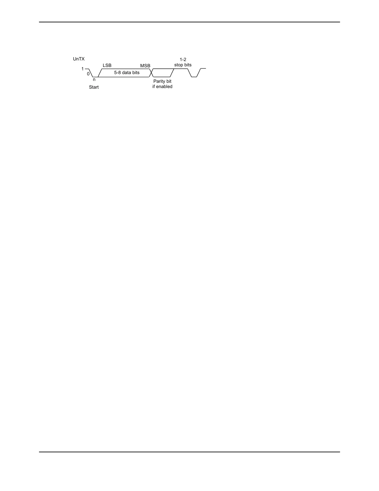
Figure 16-2. UART Character Frame
1
0
5-8 data bits
LSB
MSB
Parity bit
if enabled
1-2
stop bits
UnTX
n
Start
16.3.2 Baud-Rate Generation
The baud-rate divisor is a 22-bit number consisting of a 16-bit integer and a 6-bit fractional part.
The number formed by these two values is used by the baud-rate generator to determine the bit
period. Having a fractional baud-rate divisor allows the UART to generate all the standard baud
rates.
The 16-bit integer is loaded through the UART Integer Baud-Rate Divisor (UARTIBRD) register
(see page 1184) and the 6-bit fractional part is loaded with the UART Fractional Baud-Rate Divisor
(UARTFBRD) register (see page 1185). The baud-rate divisor (BRD) has the following relationship
to the system clock (where BRDI is the integer part of the BRD and BRDF is the fractional part,
separated by a decimal place.)
BRD = BRDI + BRDF = UARTSysClk / (ClkDiv * Baud Rate)
where UARTSysClk is the system clock connected to the UART, and ClkDiv is either 16 (if HSE
in UARTCTL is clear) or 8 (if HSE is set). By default, this will be the main system clock described
in “Clock Control” on page 230. Alternatively, the UART may be clocked from the internal precision
oscillator (PIOSC), independent of the system clock selection. This will allow the UART clock to be
programmed independently of the system clock PLL settings. See the UARTCC register for more
details.
The 6-bit fractional number (that is to be loaded into the DIVFRAC bit field in the UARTFBRD register)
can be calculated by taking the fractional part of the baud-rate divisor, multiplying it by 64, and
adding 0.5 to account for rounding errors:
UARTFBRD[DIVFRAC] = integer(BRDF * 64 + 0.5)
The UART generates an internal baud-rate reference clock at 8x or 16x the baud-rate (referred to
as Baud8 and Baud16, depending on the setting of the HSE bit (bit 5) in UARTCTL). This reference
clock is divided by 8 or 16 to generate the transmit clock, and is used for error detection during
receive operations. Note that the state of the HSE bit has no effect on clock generation in ISO 7816
smart card mode (when the SMART bit in the UARTCTL register is set).
Along with the UART Line Control, High Byte (UARTLCRH) register (see page 1186), the UARTIBRD
and UARTFBRD registers form an internal 30-bit register. This internal register is only updated
when a write operation to UARTLCRH is performed, so any changes to the baud-rate divisor must
be followed by a write to the UARTLCRH register for the changes to take effect.
To update the baud-rate registers, there are four possible sequences:
■ UARTIBRD write, UARTFBRD write, and UARTLCRH write
■ UARTFBRD write, UARTIBRD write, and UARTLCRH write
■ UARTIBRD write and UARTLCRH write
■ UARTFBRD write and UARTLCRH write
1165June 18, 2014
Texas Instruments-Production Data
Tiva
™
TM4C1294NCPDT Microcontroller
 Loading...


