9.3.5 Configuring Channel Assignments
Channel assignments for each μDMA channel can be changed using the DMACHMAPn registers.
Each 4-bit field represents a μDMA channel.
Refer to Table 9-1 on page 680 for channel assignments.
For example, to use UART1 RX on channel 8, configure the CH8SEL bit in the DMACHMAP1 register
to be 0x1. If a peripheral is enabled on two different channels, the μDMA channel that has the highest
priority for that peripheral takes precedence. Thus, if UART 1 RX is enabled on both channel 8 and
channel 22, the UART1 RX channel 22 priority needs to be lowered before channel 8 UART1 RX
can be accessed by the μDMA.
9.4 Register Map
Table 9-13 on page 701 lists the μDMA channel control structures and registers. The channel control
structure shows the layout of one entry in the channel control table. The channel control table is
located in system memory, and the location is determined by the application, thus the base address
is n/a (not applicable) and noted as such above the register descriptions. In the table below, the
offset for the channel control structures is the offset from the entry in the channel control table. See
“Channel Configuration” on page 683 and Table 9-3 on page 684 for a description of how the entries
in the channel control table are located in memory. The μDMA register addresses are given as a
hexadecimal increment, relative to the μDMA base address of 0x400F.F000. Note that the μDMA
module clock must be enabled before the registers can be programmed (see page 385). There must
be a delay of 3 system clocks after the μDMA module clock is enabled before any μDMA module
registers are accessed.
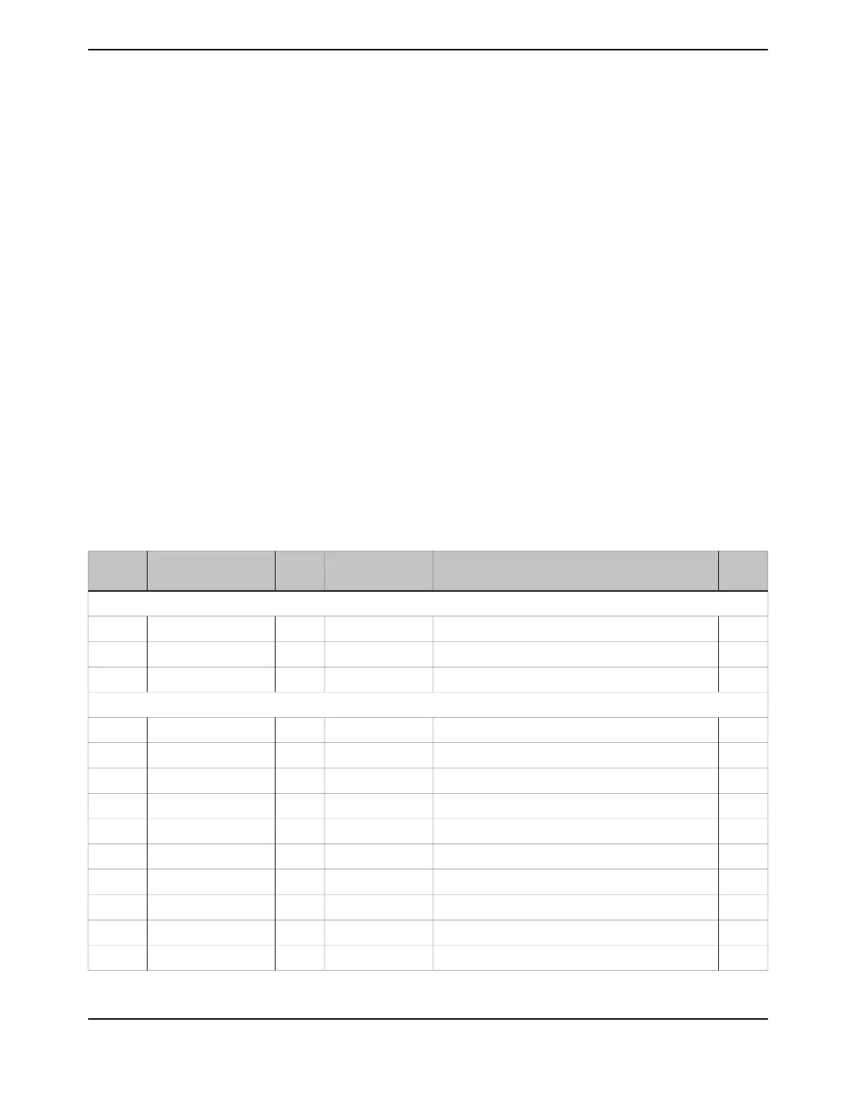
Table 9-13. μDMA Register Map
See
page
DescriptionResetTypeNameOffset
μDMA Channel Control Structure (Offset from Channel Control Table Base)
703DMA Channel Source Address End Pointer-RWDMASRCENDP0x000
704DMA Channel Destination Address End Pointer-RWDMADSTENDP0x004
705DMA Channel Control Word-RWDMACHCTL0x008
μDMA Registers (Offset from μDMA Base Address)
710DMA Status0x001F.0000RODMASTAT0x000
712DMA Configuration-WODMACFG0x004
713DMA Channel Control Base Pointer0x0000.0000RWDMACTLBASE0x008
714DMA Alternate Channel Control Base Pointer0x0000.0200RODMAALTBASE0x00C
715DMA Channel Wait-on-Request Status0x03C3.CF00RODMAWAITSTAT0x010
716DMA Channel Software Request-WODMASWREQ0x014
717DMA Channel Useburst Set0x0000.0000RWDMAUSEBURSTSET0x018
718DMA Channel Useburst Clear-WODMAUSEBURSTCLR0x01C
719DMA Channel Request Mask Set0x0000.0000RWDMAREQMASKSET0x020
720DMA Channel Request Mask Clear-WODMAREQMASKCLR0x024
701June 18, 2014
Texas Instruments-Production Data
Tiva
™
TM4C1294NCPDT Microcontroller
 Loading...


